AOS
Elastic VM Storage
Based on:
PC
7.5
|
AOS
7.5
|
AHV
11
» Download this section as PDF (opens in a new tab/window)
Hyperconverged infrastructure significantly streamlines operations by integrating compute, networking, and storage into a single cluster. However, individual clusters can scale at different rates. This leads to scenarios where compute demand surges in one cluster while storage capacity remains underutilized in another. Traditionally, storage for a VM on Nutanix was generally restricted to the same cluster as its compute resources. However, with the introduction of Elastic VM Storage in AOS 7.5 and AHV 11, a virtual machine can now utilize compute from one hyperconverged cluster while drawing storage from a different one. This capability promotes balanced resource utilization, optimizes infrastructure investment, and enhances overall ROI.
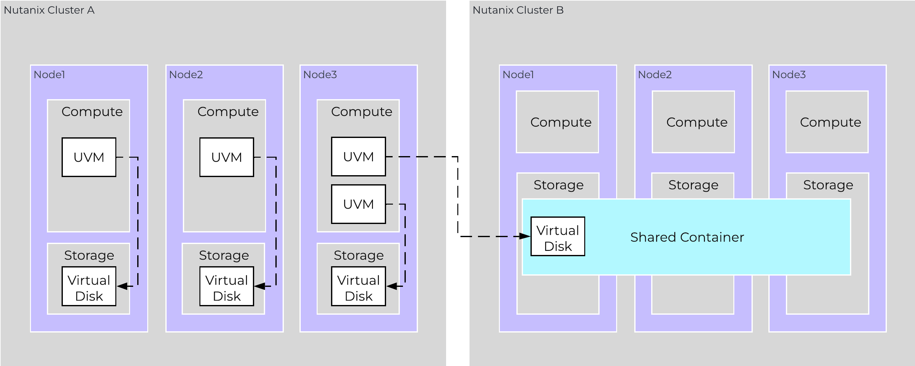 Elastic VM Storage VM overview
Note
Note
In order to leverage Elastic VM Storage, the clusters involved must be registered to the same Prism Central instance. This is sometimes called the same Availability Zone or Domain.
The illustration above demonstrates the architecture of Elastic VM Storage. In this scenario, a virtual machine utilizes compute resources from Cluster A (shown on the left) while accessing storage resources from Cluster B (shown on the right) through the use of a “shared container”. This configuration is ideal when Cluster A possesses ample compute power but limited storage capacity, whereas Cluster B offers significant storage availability to compensate.
Below are just a few of the services that are part of the overall Nutanix Platform and are key to the functionality of Elastic VM Storage.
Guru
- Key Role: Coordinates Prism Element (PE) cluster pairing
- Description: Provides the Remote Procedure Calls (RPCs) that will be used by Metropolis to pair and unpair Prism Elements.
Cerebro
Narsil
- Key Role: Local PE virtualization management
- Description: Delivers VM lifecycle management, cross-cluster migration, disaster recovery orchestration, and guest tools management. It serves as a bridge between other platform services (Acropolis, Ergon, etc.), exposing internal and external APIs for VM management.
Metropolis
- Key Role: Prism Central VM management service
- Description: Serves as the Prism Central (PC) counterpart to Acropolis and Narsil, coordinating VM operations across multiple Prism Elements (PE). It implements the v4 VM APIs, manages VM policies, and oversees OVA lifecycle and cross-cluster VM operations.
IDF (Insights Data Fabric)
- Key Role: Config and time series store
- Description: Serves as a database on PE and PC for storing configuration, metrics, performance information, alerts, event data, and cluster pairing state. The local PE IDF syncs information to IDF running on PC, to ensure consistency in operations and management. You can find more info on IDF on the Book of Prism page.
Stargate
For a list of other Nutanix cluster services, visit the Book of Basics Components page.
Elastic VM Create I/O Path
The standard virtual machine storage I/O path typically starts and ends within a single cluster. However, with Elastic VM Storage, compute is executed on the designated NCI cluster where the VM resides, whether initiated via API or the Prism Central UI. Meanwhile, storage operations are proxied from the NCI cluster housing compute to a separate hyperconverged cluster chosen during the VM creation process. This architecture utilizes a shared container on the remote cluster to host the virtual disks attached to the VM.
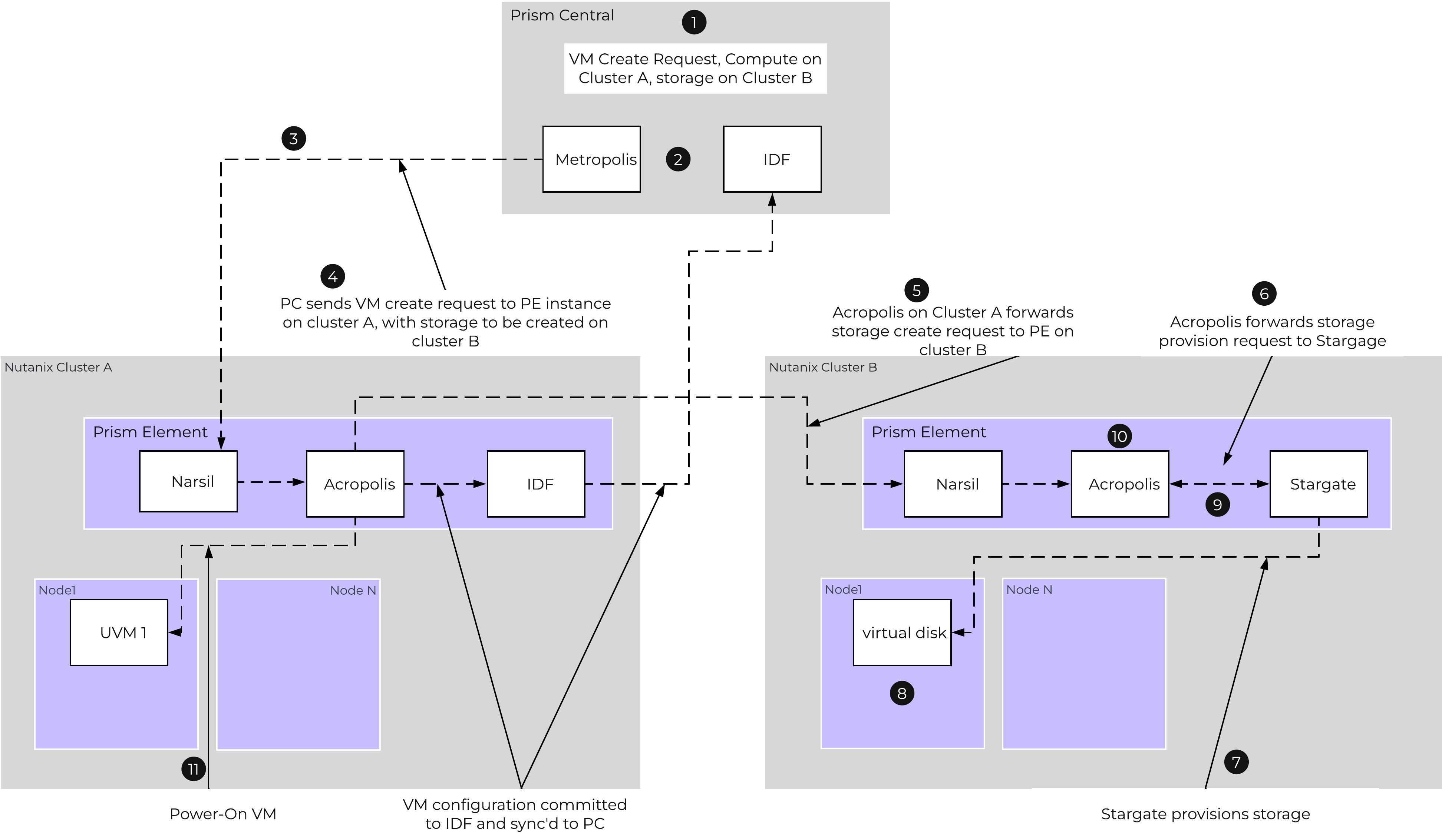 Elastic VM Create Workflow
The VM create data path would look like the following:
- PC: The operator initiates the VM creation request via Prism Central, specifying Cluster A for compute and Cluster B for storage during the workflow.
- PC: A check is done automatically by PC to determine if there is an existing partnership between Cluster A and Cluster B; if none exists, PC initiates a back-end pairing process between the clusters.
- PC: A call is made from Prism Central to Cluster A, requesting the VM creation. The UUID for Cluster B will be passed to Cluster A to assist in creating the virtual disks.
- Cluster A: A call is made to Acropolis to create the VM, passing it details that vDisk storage should exist on Cluster B
- Cluster A: Acropolis through RPCs calls reaches out to Cluster B, requesting the creation of storage for the VM.
- Cluster B: Receives the request and initiates a call to its local Acropolis service to create the vm disks.
- Cluster B: Acropolis makes a call to Stargate requesting the creation of the disks within a local shared container.
- Cluster B: A local access entry is made by the CVM to allow Stargate to permit the virtual machine access to its virtual disk(s) from Cluster A. This ensures the owning virtual machine can connect to the disk.
- Cluster B: Stargate upon creating the disks will let Acropolis know and an acknowledgement will be sent to the Acropolis service on Cluster A that the disks were created.
- Cluster A: Acropolis will then commit the VM configuration information to its local IDF and then sync that information to the IDF on PC.
- Cluster A: The Administrator/Operator can now power-on the VM.
Note
Pro Tip
The latency between the two clusters ideally should be 2ms or less (5ms max). This aligns to the traditional hyperconverged node placement requirements when compute and storage reside on the same NCI cluster. Anything over 5ms will generate NCC alerts and could impact application performance and user experience for write-centric workloads.
Elastic VM Data I/O Path
The data I/O path for virtual machines utilizing elastic storage mirrors that of standard VMs. Compute and storage communication continues to use iSCSI; however, Frodo intercepts these calls to route storage requests to the remote cluster. This seamless operation highlights the advantages of a deeply integrated architecture.
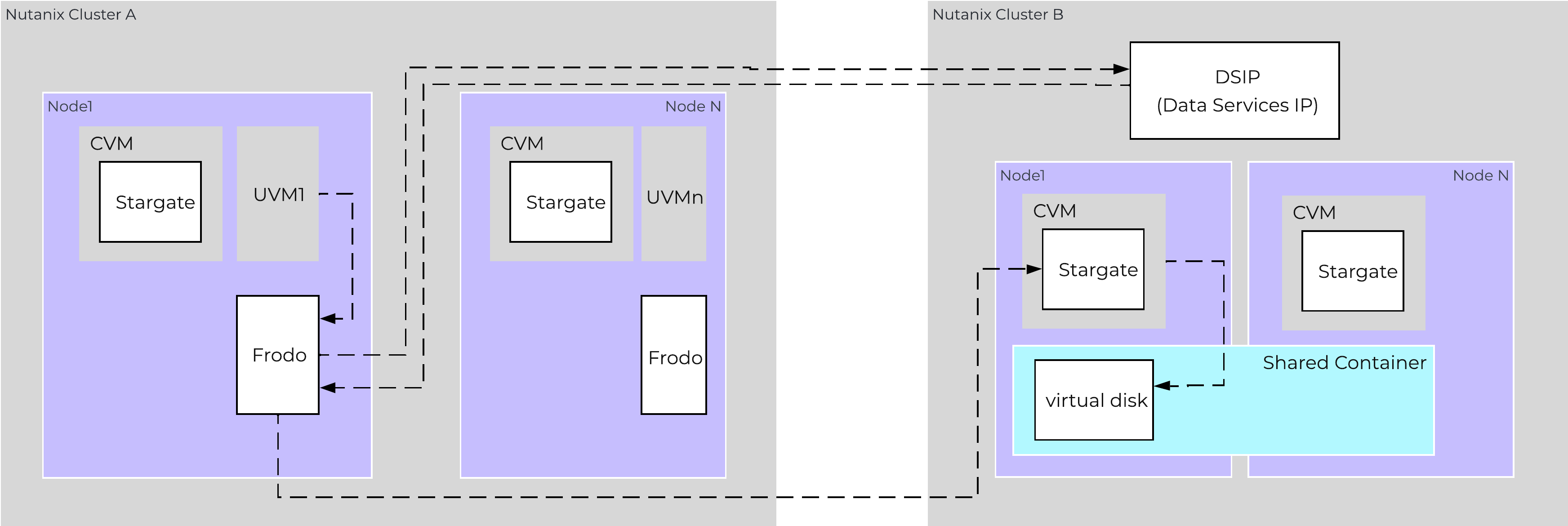 Elastic VM Data Path
- Cluster A: The UVM power-on is initiated, whether from PC or API.
- Cluster A: The UVM sends send a SCSI request for access to its local block storage (aka vDisk).
- Cluster A: Frodo redirects the request to the DSIP (data services IP) on the cluster owning the virtual disks.
- Cluster B: The DSIP redirects the request to the appropriate Stargate. Node 1 on cluster B, in this example.
- Cluster A: Frodo initiates an iSCSI login request to redirected Stargate on Cluster B.
- Cluster B: Stargate confirms the initiator IQN has been whitelisted (the whitelisting is done automatically during initial VM creation).
- Cluster B: Stargate authenticates the login request.
- Cluster A: UVM power-on completes and storage I/O begins.
Elastic VM Snapshot
The creation of a snapshot for an elastic virtual machine is slightly different than a traditional non-elastic virtual machine. The process needs to leverage details from two clusters: the cluster that contains the storage for the virtual disk (Cluster B) and the cluster that holds the compute (Cluster A). The process to initiate the snapshot is the same and operationally the process will look the same to a user of the platform.
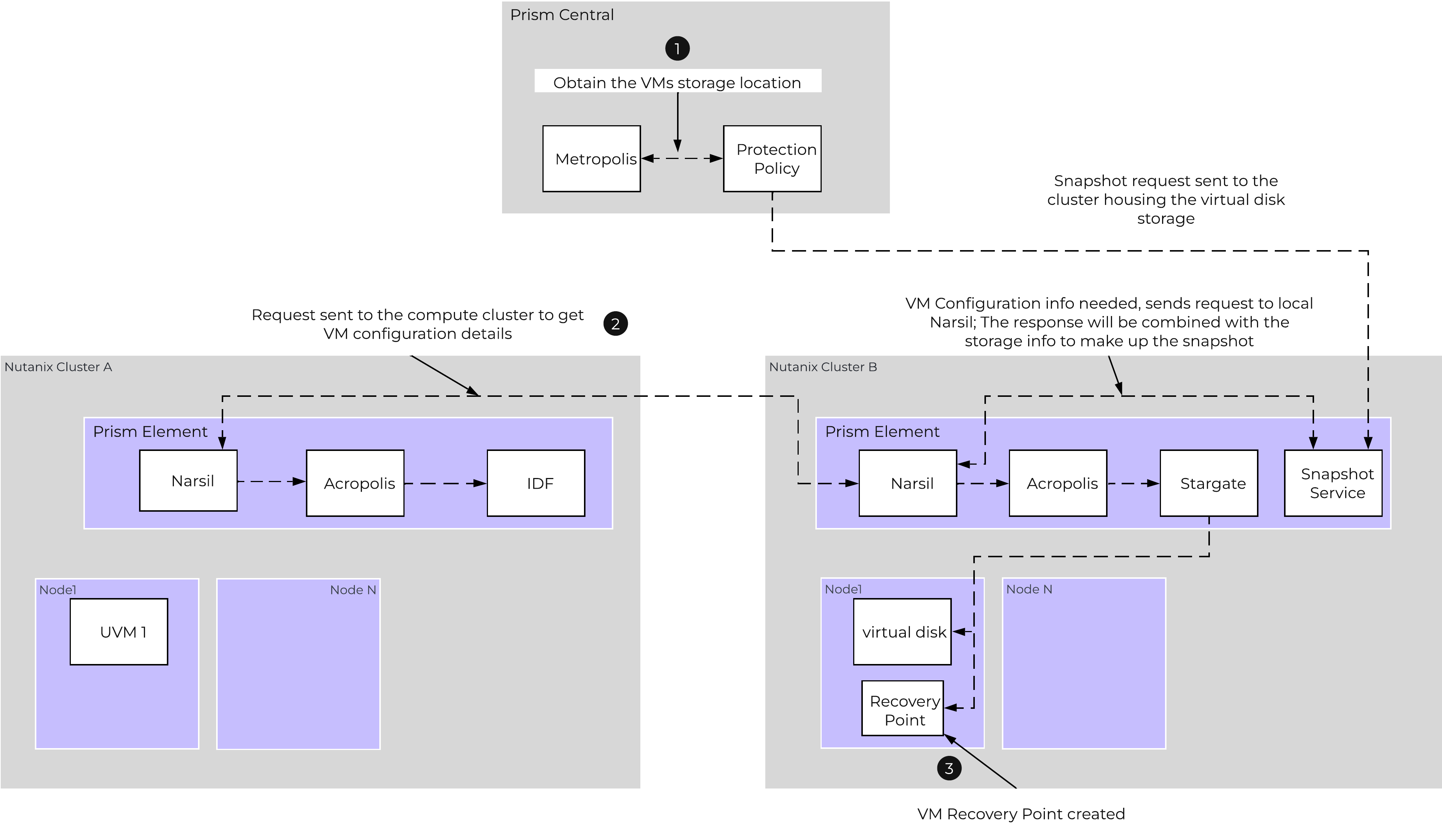 Elastic VM Snapshot Create
- PC: Metropolis is queried from PC to gather the storage location for the VM during a recovery point creation request. This is needed as the snapshot needs to be created where the VM data is stored
- Cluster B: Narsil on cluster B reaches out to cluster A to retrieve the VM configuration information.
- Cluster B: The snapshot service on cluster B combines the VM configuration details, along with the storage snapshot (Cerebro) to create a Recovery Point.
- Cluster B: The existing vDisk is marked by Stargate as immutable as part of the snapshot create process.
- Cluster B: A New live vDisk is created by Stargate for new I/O.
Note
Pro Tip
With Elastic VM Storage, the VM recovery occurs on the cluster providing the storage (ie: Cluster B here). This is a critical detail to remember when restoring a VM from a recovery point.
©2025 Nutanix, Inc. All rights reserved. Nutanix, the Nutanix logo and all Nutanix product and service names mentioned are registered trademarks or trademarks of Nutanix, Inc. in the United States and other countries. All other brand names mentioned are for identification purposes only and may be the trademarks of their respective holder(s).