» Download this section as PDF (opens in a new tab/window)
Today’s IT environments have fundamentally changed. Workloads are no longer confined to a single datacenter; they are distributed across multiple sites and clouds, in a truly hybrid and multicloud approach. This transformation brings agility and flexibility, but it also introduces new challenges. Operational silos complicate the management of multi-tenant infrastructures. Security must now extend across every layer, from the application to the network. Speed of execution is critical, as teams are expected to operate at cloud velocity without slowing down the business. Day-to-day operations are becoming increasingly complex, from deployments to migrations. Application mobility has also become an unavoidable reality, with workloads that must move freely between environments. In the face of this complexity, we must rethink how networks are designed, secured, and operated.
It is in this context that Software-Defined Networking (SDN) emerged. The core idea of SDN is to separate the control plane from the data plane, centralizing network intelligence while maintaining distributed execution at scale. SDN provided concrete answers to modern challenges by introducing programmability that replaces scattered manual configurations, automation that accelerates the delivery of network services, unified visibility that enables deeper understanding and protection of application flows, and abstraction that allows teams to operate at the level of business needs rather than IP addresses and VLANs. With SDN, the network becomes an agile service, aligned with the expectations of cloud and modern applications.
This is precisely where Nutanix Flow comes into play. By combining Flow Virtual Networking (FVN) and Flow Network Security (FNS), Flow provides an integrated approach to connectivity and security in Nutanix environments. FVN delivers the virtual networking infrastructure including VPCs, subnets, gateways, extensions, and hybrid interconnects. FNS brings distributed and stateful security controls natively embedded in the Nutanix hypervisor, AHV. Together, these components enable the design of agile, secure, and multicloud-ready architectures without unnecessary complexity or reliance on traditional appliances. Flow represents the vision of a network that is simple, elastic, and secure, built to support application mobility and continuous innovation. To begin this journey, we will first define what Flow is, why it was created, and how it fits into the broader Nutanix platform.
Flow Virtual Networking (FVN) and Flow Network Security (FNS) are two complementary components that work together to deliver and secure software-defined networks in a uniform way across the Nutanix hybrid multi-cloud landscape. They are designed with a simple but ambitious vision: to bring networking and security to the same level of simplicity and automation that Nutanix has achieved for compute and storage. Traditional networks are complex, rigid, and heavily dependent on specialized appliances. Flow removes this barrier by embedding networking and security directly into the Nutanix platform.
The value proposition of Flow rests on three pillars. First, it simplifies operations by providing a unified framework to manage both connectivity and security across virtualized environments. Second, it enables application-centric architectures where policies and connectivity follow workloads, regardless of where they are deployed. Third, it prepares enterprises for hybrid and multicloud realities, extending secure connectivity beyond the boundaries of a single datacenter. This design philosophy has resulted in a platform that enables customers to move faster, operate more securely, and reduce the operational overhead typically associated with networking and security infrastructure.
While FVN is focused on building and extending networks, FNS is focused on securing them. Together they form a complete solution for application connectivity and protection. FVN provides the constructs required to build modern virtual networks. It introduces VPCs, overlay subnets, gateways, VPN connectivity, BGP-based dynamic routing, and load balancing. These capabilities allow Nutanix environments to connect seamlessly to each other, to external datacenters, and to public cloud resources.
FNS delivers distributed, stateful firewalling natively on AHV hosts. It enforces microsegmentation policies between workloads and reduces lateral movement risks without requiring external firewalls for east-west traffic.
AHV leverages Open vSwitch (OVS) to present traditional VLAN networks, with each node running an instance of OVS via a default bridge, called br0. You must attach physical interfaces to br0 to act as uplinks, either as standalone uplinks, in active/passive or active/active aggregates. Additional bridges can be created as needed. An additional bridge, not managed by OVS, called virbr0, also exists to facilitate internal AOS networking.
Across all of the nodes in a cluster, the bridges are aggregated into a virtual switch. The default virtual switch is called vs0. To facilitate this, each host in the cluster must have identical uplink port configuration. The physical switch ports for each host should also be configured identically, presenting the same VLANs to each host’s uplinks.
Subnets are added to the virtual switch and defined by a VLAN tag. This makes the subnet available on every host’s bridge. VMs are connected to subnets, which connect by way of tap ports.
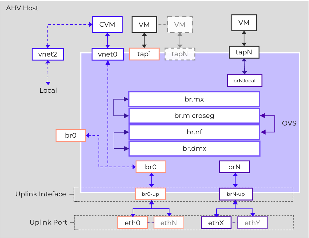
Nutanix Flow is implemented as extensions of the base AHV networking systems, so an understanding of that base networking is valuable in understanding the data plane.
Nutanix Flow is structured in a familiar three-plane architecture (Management, Control, Data) that enhances the OVS-based networking on the AHV hosts with added functionalities through the Open Virtual Network (OVN) project.
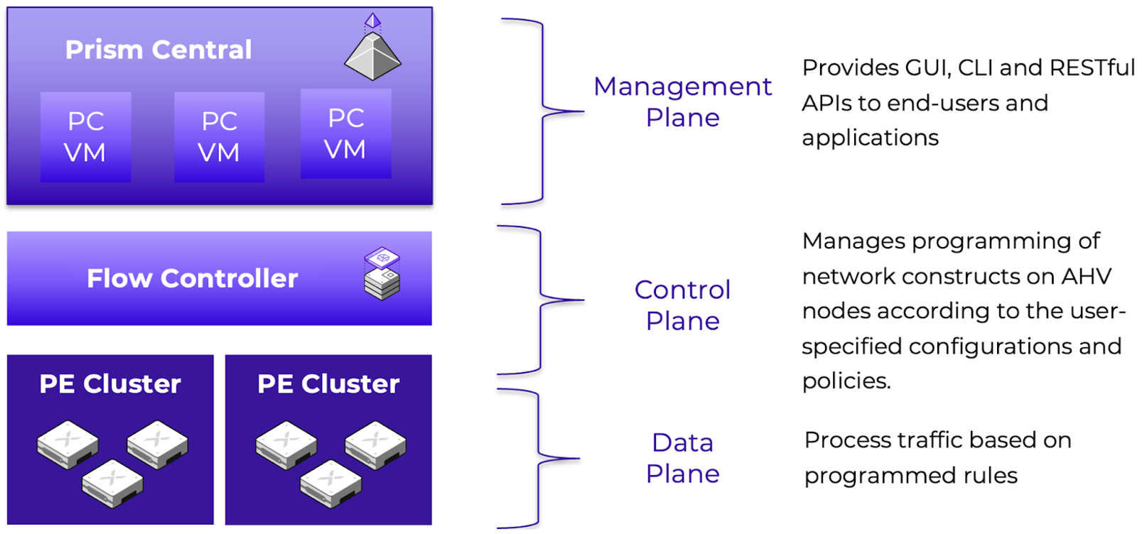
The Management Plane is delivered via Prism Central, the single management plane for Nutanix clusters, ensuring a consistent operational model for administrators. Prism Central provides GUI, API, and CLI interfaces for CRUD operations and monitoring. There are four primary services that work together to provide the management plane:
The Control Plane has a centralized component called the Flow Controller, formerly Network Controller, formerly Advanced Network Controller (ANC), as well as a distributed component that runs on each AHV host. The Flow Controller is delivered as a set of containerized services. You can deploy the Flow Controller in integrated mode which leverages the built-in Prism Central Container Microservices Platform (CMSP). Alternatively, standalone mode deploys the Flow Controller on SMSP (Services Microservices Platform) using three worker VMs and two load balancer VMs. The Flow Controller creates virtual overlay networks as an abstraction of the underlay (VLAN networks), managing network services.
The main services of the control plane include:
Hermes is the service that manages OVN configuration, receiving updates from Atlas and converting them to OVN logical configuration, and sending that configuration to the OVN components. Hermes also collects metrics from each AHV host’s OVS instance. Hermes consists of two sub-components: anc-hermes is the main service, and anc-mysql (MariaDB) stores the Hermes configuration. These service names reflect the prior Atlas Network Controller naming, ANC.
Open Virtual Network (OVN) is responsible for programming the data plane elements on the AHV hosts. OVN has centralized components hosted on the network controllers, and distributed components hosted on each AHV host. On the Network Controller, there are two main components: anc-ovn which runs the ovn-northd service as well as the OVN NorthboundDB and SouthboundDB, and anc-policydb which handles mapping connections to policies for visualizations and hitlogs. On each AHV host, the ovn-controller service is responsible for taking configuration from the OVN SouthboundDB and programming the data plane elements on the local hypervisor accordingly.
The Data Plane is fully distributed, allowing implementation of the network and security constructs across the AHV hypervisor nodes. This allows for an efficient, resilient environment that avoids bottlenecks and scales in capacity as clusters grow. It comprises the following parts:
This tight integration means that Flow is not an external add-on, but rather a native capability of the Nutanix Cloud Platform. Administrators can create VPCs, configure gateways, define security policies, and monitor traffic without leaving Prism Central. For customers, this results in a consistent operational experience across compute, storage, networking, and security.
In the following sections, we will discuss the specifics of the Flow Virtual Networking data plane implementation.
Nutanix Flow is able to deliver both functional multitenancy and administrative multitenancy through this three-plane architecture.
Functional tenancy defines whether the environment is logically partitioned to provide private network resources to disparate groups. These groups can be internal groups, such as departments, development teams, or business units. They can also be external groups, such as clients consuming resources from a service provider. Functional multitenancy in Flow is similarly implemented through the data plane implementation of Virtual Private Clouds, allowing individual groups to have their own networks as well as their own security policies.
Administrative tenancy defines whether administrative access and functions are made available to multiple groups to manage their own resources. This can also be internal, where RBAC is used to grant selective access to staff members via a single identity provider (IdP), or external, where multiple IdPs are configured, enabling external clients to access the environment. Administrative external multitenancy is typically only found in service provider environments. Prism Central enables administrative multitenancy through configuration of multiple identity providers and through assigning resources to Projects.
Nutanix Flow extends the capabilities of the Nutanix Cloud Platform, using the flexibility of Software Defined Networking to further existing capabilities. For example:
Enabling Flow Virtual Networking introduces two new types of Subnet which are provisioned on brAtlas. These are Controller-Managed VLAN Subnets and Overlay Subnets. The Network Controller provisions and manages these subnets as OVN logical switches. When a VM NIC is connected to an FVN subnet, a Logical Switchport is defined which maps the vNIC to the logical switch.
FVN enables provisioning and managing VLAN-backed subnets via the Network Controller. These Controller-managed VLAN-backed networks are referred to simply as VLAN Subnets. Enabling FVN relabels the existing AHV-managed VLANs configured on br0/vs0 as VLAN Basic Subnets.
When a controller-managed VLAN Subnet is created, a logical switchport, called a localnet port, is created to connect brAtlas to br0 to present that VLAN to the Network Controller. Configuring a VLAN as controller-managed enables the VLAN to provide external connectivity for VPCs, as well as enabling VMs residing on that VLAN to be secured via Flow Network Security Next-Gen.
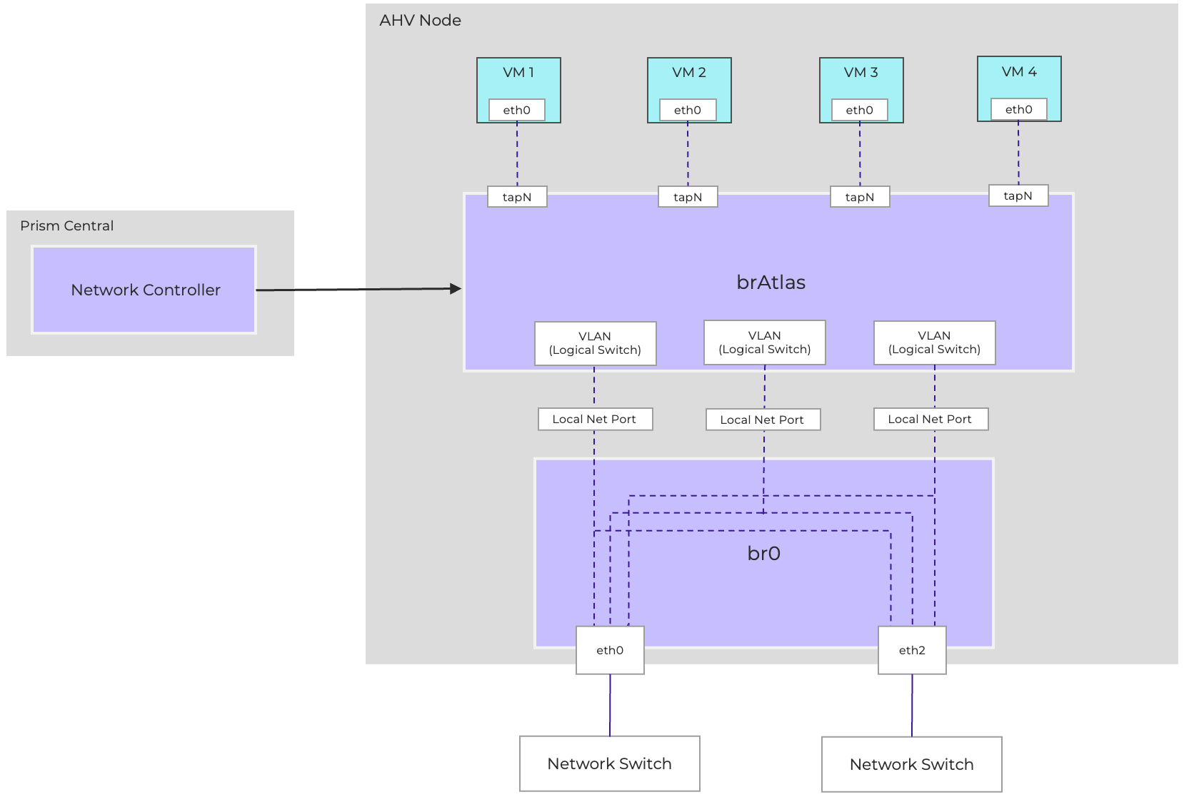
Diagram showing connectivity between brAtlas and br0 for VLAN-backed connectivity.
VLAN-backed subnets provide Layer 2 connectivity through VLANs established on the physical network. As a result, all virtual machines (VMs) connected to the same VLAN-backed subnet are Layer 2 adjacent. Connectivity between two VMs on the same host and the same VLAN-Backed subnet occurs entirely within the local bridges. If the VMs are on different hosts, the Ethernet frames will be sent to the destination VM via the physical infrastructure using standard Ethernet framing and switching.
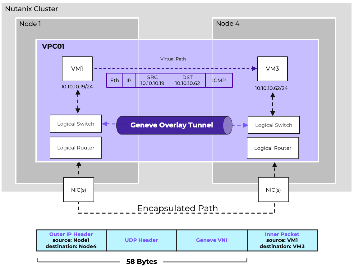
Overlay Subnets are software-defined layer-2 networks that operate independently of the physical network (the underlay). This allows workloads to be placed anywhere in the environment while maintaining consistent addressing and connectivity, regardless of the underlying VLAN or switch configuration. The overlay ensures flexibility and simplifies operations, since administrators no longer need to manage large numbers of VLANs across the physical fabric.
Flow leverages Geneve network encapsulation to manage and transport overlay traffic. Each brAtlas bridge (and therefore each host) acts as a Geneve Tunnel Endpoint (TEP). When two VMs in the same Overlay subnet but residing on different hosts need to communicate, the host and bridge at the source will encapsulate the packet with Geneve, and the host and bridge at the destination will decapsulate and deliver it.
When VMs are in the same VPC and on the same AHV host, the IP traffic does not leave that host.
For communication between two VMs in the same Overlay subnet but situated on separate hosts, the process involves encapsulation and decapsulation using Geneve. Specifically, the source host and bridge will encapsulate the packet with Geneve, and the destination host and bridge will then decapsulate it before delivery.
Overlay networks are able to span multiple AHV clusters, provided that the clusters are managed by the same Prism Central and Network Controller. All hosts must be able to communicate via UDP port 6081 to allow Geneve traffic. By default, Overlay traffic traverses vs0/br0, using the main AHV hypervisor IP as the TEP address, but this is configurable. If additional physical uplink ports are available, an additional virtual switch can be created and IPs can be assigned to each host on that virtual switch. The cluster can then be configured to use the alternative virtual switch for Geneve TEP traffic via acli, the command line interface for cluster networking, with the command:
net.set_vpc_east_west_traffic
For more information on controlling the TEP traffic, refer to the relevant section of the AHV Admin Guide.
Flow Virtual Networking and the underlying OVN and OVS subsystems implement certain traffic handling procedures to more efficiently handle overlay traffic and limit unnecessary broadcast traffic.
OVN maintains a table of MAC to Chassis mappings, called the Port_Binding table, which identifies the AHV host responsible for each vNIC (called a logical port by OVN/OVS), and includes statically defined MAC and IP information. A second table, the MAC_Binding table, tracks MAC to IP associations learned through observing ARP traffic. This information is tracked in a database on the Network Controller which is continuously replicated to each participating AHV host. Additionally, each host maintains a table with information about all other hosts, allowing Geneve tunnels to be established to any remote endpoint without requiring additional lookups.
When a VM needs to send traffic to another VM on the same subnet, and the guest OS does not already have an ARP entry for the destination, the VM will generate an ARP request. On a traditional physical underlay network, this ARP request would be flooded to all hosts in the subnet. However, on an Overlay Subnet, ARP Suppression is used, whereby the local OVS instance on the AHV host will forge an ARP reply using the data replicated from the Network Controller. This reduces the amount of broadcast traffic within the environment. Once the VM receives the ARP reply, traffic is either locally switched within the AHV host if the VMs reside on the same host, or encapsulated and sent to the appropriate destination host via a Geneve tunnel.
Broadcast traffic is handled via a process called ingress replication. The source AHV host will send one encapsulated copy of the frame to be flooded to each remote chassis, and the remote chassis will distribute the frame locally as needed to the relevant VMs connected to the FVN subnet. This reduces the traffic traversing the physical underlay while still ensuring proper delivery of the broadcast frame to all VMs in the Subnet.
Unknown Unicast traffic will be dropped unless a Subnet Extension is configured for that Overlay Subnet, in which case all Unknown Unicast traffic will be forwarded to the VTEP Gateway.
Multicast Traffic will function within a single Overlay Subnet, but there is no support for IGMP Snooping within overlay subnets.
Choosing between Subnet types depends on operational needs. In most cases, Overlay subnets simplify operations, while VLAN-backed subnets are reserved for specific integration points.
Overlay Subnets enable workloads to be distributed across the Controller-managed cluster freely, allowing for full workload mobility and network design flexibility. New Overlay Subnets can be provisioned immediately, either manually or via automation, without any additional configuration on the underlay. Most importantly, they connect workloads to Virtual Private Clouds. They also enable additional features including Network Load Balancing and Flow Network Security Next-Gen.
VLAN Subnets are required to provide external connectivity to Virtual Private Clouds. Additionally, VLAN Subnets are recommended for any workloads requiring direct layer-2 adjacency to resources that cannot be placed directly on an Overlay subnet (physical resources or VMs outside of the domain of the Network Controller). Subnet Extensions can be used to bridge an Overlay subnet to a physical VLAN, but this is not suitable for all use cases. VLAN Subnets are required for any workloads that wish to take advantage of Flow Network Security’s Service Insertion feature.
Flow Virtual Networking provides DHCP functionality, referred to as Nutanix IPAM. This is optional for VLAN-Backed Subnets and required for Overlay Subnets. When Nutanix IPAM is enabled for a subnet, a network, gateway, and pool of addresses must be defined. When using IPAM, administrators can also define DNS servers, a DNS domain name, DNS search domains, a TFTP server, and a boot image.
Administrators can either allow addresses to be assigned dynamically from the pool or statically assign IP addresses to VMs via Nutanix IPAM which act as a DHCP Reservation, guaranteeing address assignment. If it is preferred that the guest OS be configured with a Static IP, that is also an option. It is suggested that the VM also be statically assigned the same IP address within IPAM. There are no reserved IP addresses other than the gateway and broadcast address. Any valid IP address can be assigned to a VM, regardless of whether or not it is in the IP Pool allocated for dynamic assignment.
DHCP leases are considered to be infinite; there is no need to release and/or renew addresses. IP addresses are released when a VM or vNIC is removed, or when an address is manually changed.
VLAN-Backed subnets can be configured to use External IPAM, in which case Nutanix IPAM/DHCP services are not enabled, and an external DHCP server can be used if dynamic addressing is required.
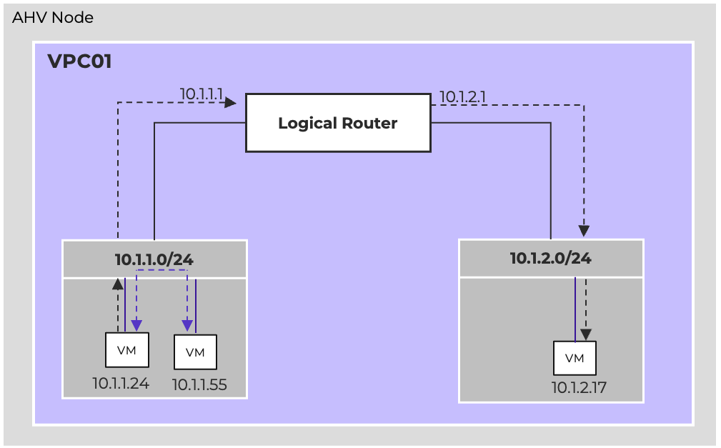
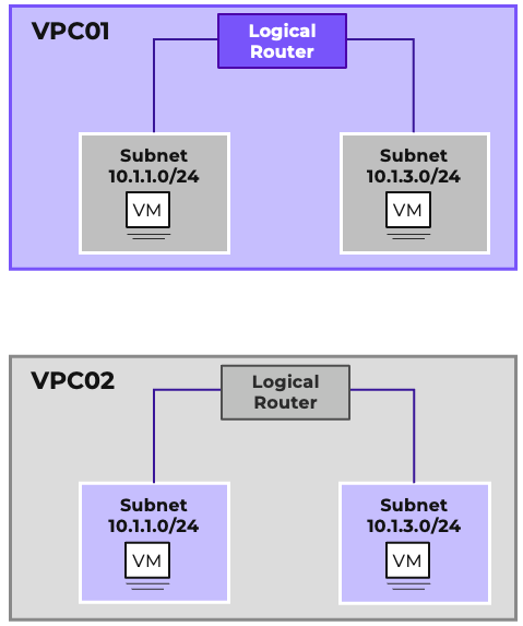
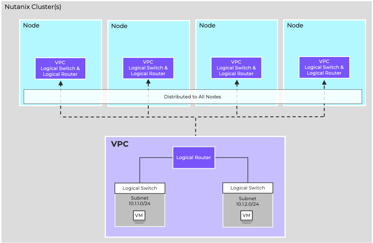
At the heart of Flow Virtual Networking is the Virtual Private Cloud, or VPC. A VPC is an isolated networking domain within the Nutanix environment, allowing tenants or applications to operate in their own dedicated space. VPCs feature a fully distributed virtual router that offers logical routing for multiple Overlay Subnets and provides north-south connectivity through External Networks. Different VPCs can share the same IP address ranges without conflict because they are isolated network domains. This overlap is common in multi-tenant and multicloud environments, where address ranges are often duplicated across various sites or customers.
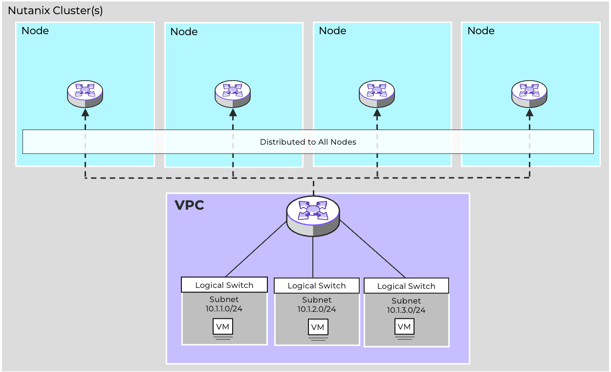
Routing decisions are made locally on the host where the traffic originates. The Network Controller ensures that the logical router state is synchronized across all hosts, so that routing behavior is consistent throughout the cluster. This distributed design enables high availability, since there is no single routing bottleneck.
In the example shown, both VPC01 and VPC02 can be configured with 10.10.1.0/24 and 10.10.2.0/24. An IP overlap model is a key enabler of workload mobility and tenant isolation. Each VPC virtual router maintains its own forwarding table and enforces separation from other VPCs. Connectivity between VPCs, if needed, is explicit and controlled, rather than implicit. This ensures that tenants remain isolated unless policies or gateways are deliberately configured to provide interconnection.
VPCs provide scale and high availability through their fully distributed, stateless architecture, implemented as an OVS logical router on each AHV node, managed centrally by OVN through the Network Controller. Each AHV host can route and switch traffic for each VPC subnet, enabling traffic to be processed as quickly and efficiently as possible. Through this stateless, distributed design, VPC throughput scales as clusters grow, while the failure of a single AHV host will not disrupt east/west connectivity for the remaining hosts.
Stateful network services for the VPC, including BGP, VPN, and VXLAN, are implemented by way of Network Gateway VMs. This disaggregation of stateful functionality from the stateless logical router allows these stateful services to be implemented without impacting the ability of the logical router to scale. We will cover the specific functionality of each network gateway type in depth in the relevant section.
Each VPC has a route table that defines how layer 3 traffic should be forwarded. There are three types of routes, which are prioritized by type. Local routes are the highest priority and indicate directly-connected traffic for VPC Overlay Subnets. Static routes are next, and allow VPC administrators to define which external network is selected for different network destinations. Dynamic routes are learned via BGP and allow for routes to be automatically learned from the physical infrastructure. Refer to the Dynamic Routing section for more details on how BGP is implemented in Flow Virtual Networking.
Additionally, Network Policies allow for policy-based routing, both for east/west and north/south traffic.
Reroute policies redirect traffic to a destination within the VPC, while forward policies redirect traffic to an external destination. These policies can identify traffic by source, destination, port, and/or protocol. Refer to the Network Policies section for more details and configuration examples.
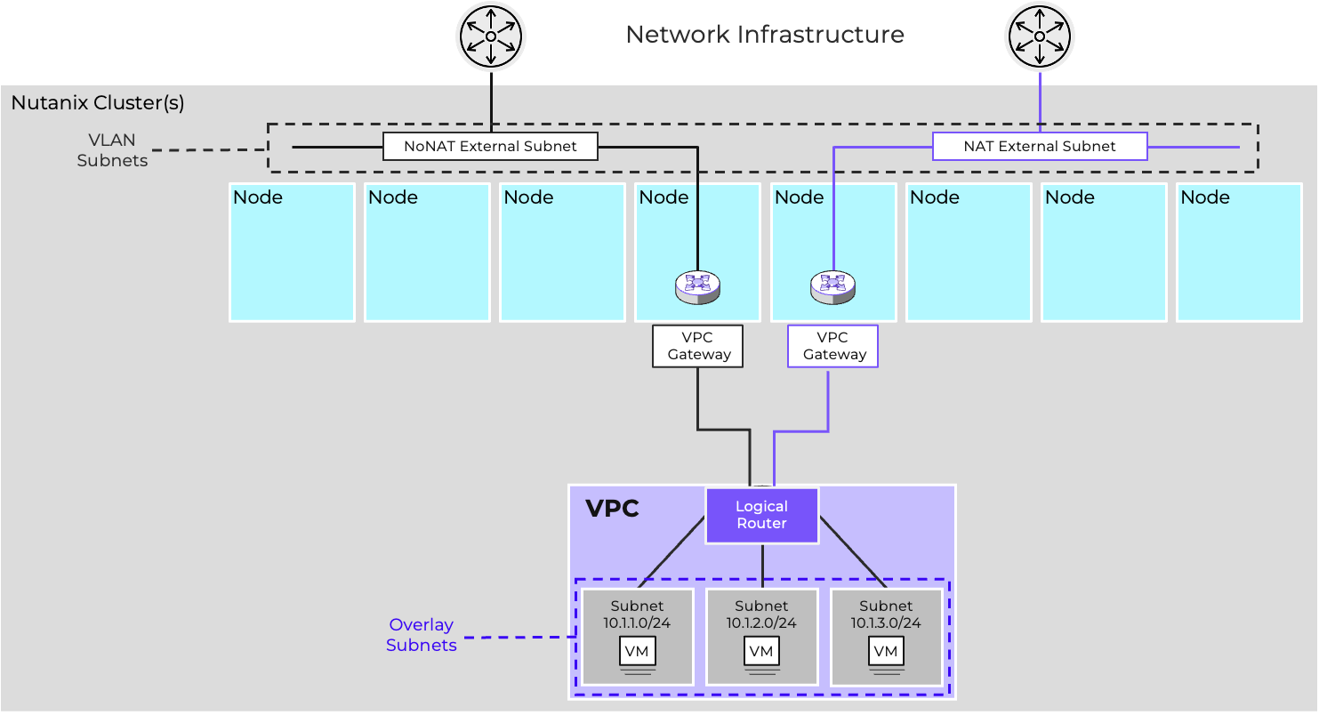
VPC designs can be either single-tier or two-tier. In a single-tier architecture, each VPC is directly connected to the network infrastructure via VLAN-backed external networks.
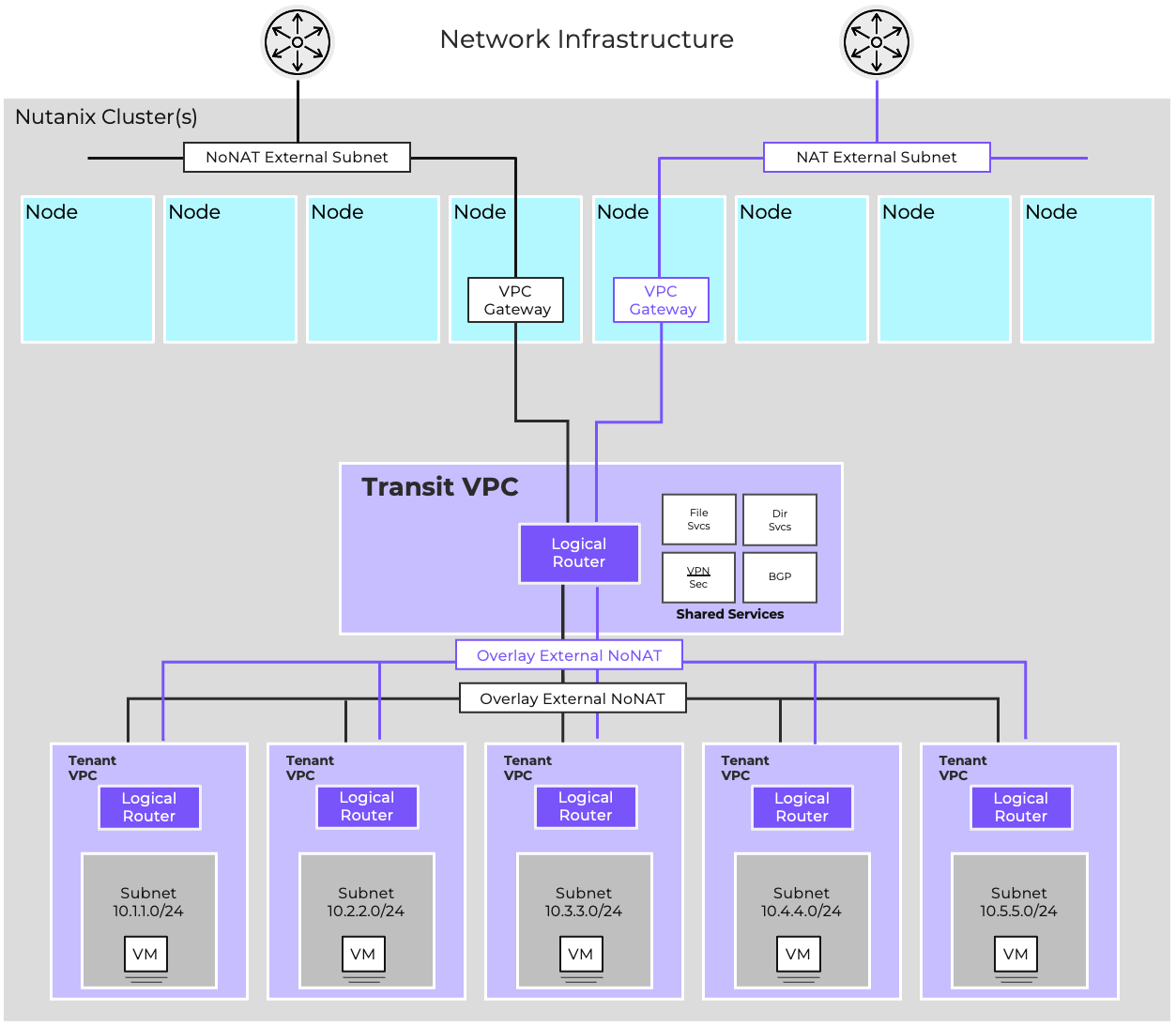
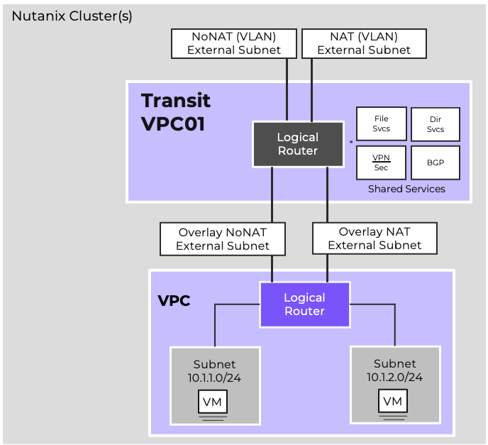
Two-tier architectures leverage Transit VPCs with a specially configured VPC providing centralized north/south connectivity for one or more connected VPCs. A Transit VPC is often used in situations where functional multitenancy is required, such as in service provider environments with multiple isolated clients, software development teams that need to provide isolated networking for multiple developers and/or environments, or organizations with specialized workloads requiring isolation.
When a new subnet is created or a gateway is configured, the Network Controller automatically generates the necessary control plane entries and distributes them to the relevant hosts. Each VPC has its own logical router, which provides the routing domain for its subnets. The Network Controller ensures these logical routers are instantiated consistently across the cluster, without manual intervention.
Flow Virtual Networking deployments start with the creation of a VPC. A VPC defines an isolated routing domain that can host one or more subnets. Administrators use Prism Central to create a VPC, assign an address space, and then add subnets within it. Each subnet is associated with a specific IP range and can be configured as either an overlay or VLAN-backed subnet depending on workload requirements.
Subnets can be used to separate applications, environments, or tenants. For example, a VPC may contain distinct subnets for frontend, backend, and database tiers, all connected through the VPC’s logical router.
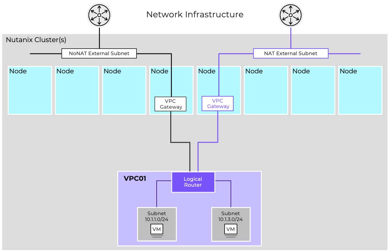
External Networks are subnets specially configured to provide external connectivity for VPCs. External networks can either be controller-managed VLAN subnets or overlay subnets created in a Transit VPC. External networks can either be NAT or Routed (NoNAT) external networks.
NAT External Networks allow VMs and subnets to remain private to the VPC, while Routed (NoNAT) External Networks allow VMs and subnets within the VPC to be directly reachable. A single VPC can be connected to one of each type of external network, and a single external network can provide connectivity to multiple VPCs.
A NAT External Network hides the private IPs of the VMs behind NAT IPs. These can either be one-to-many SNAT IPs or one-to-one NATs, called Floating IPs. SNAT IPs are used as the outbound IP for traffic egressing the VPC via the NAT External Network. Floating IPs allow a VM to be externally reachable for purposes of publishing services.
The NAT External Network provides a gateway for VMs in private overlay networks to access resources external to the VPC without being directly routable. It supports SNAT and Static NAT (Floating IP). IP addresses for NAT are allocated via the NAT External Network’s IPAM configuration.
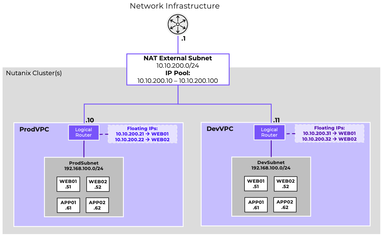
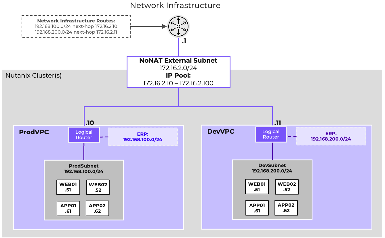
For example, in the diagram shown both ProdVPC and DevVPC use the 192.168.100.0/24 address space, and are provided external connectivity via Flow-Ext-NAT. SNAT IPs for each VPC are allocated out of the external network’s IP pool 10.10.200.10-100, with 10.10.200.10 being assigned to ProdVPC and 10.10.200.11 being assigned to DevVPC. In each VPC, the web servers are made externally reachable by assigning Floating IPs. This allows both ProdVPC and DevVPC instances to have their web servers externally reachable via unique IPs without requiring unique private addressing within the VPC. In each VPC, Web and App servers communicate via the VPC-specific instance of 192.168.100.0/24.
Routed external networks allow the IP space of the VPC to be exposed to and shared through routing. Traffic egressing the VPC via a routed network will not be NATed. As such, the VPC’s address space is no longer isolated from the address space outside the VPC, and IP overlap must be avoided. A configurable list of Externally Routable IP Prefixes (also called ERPs) defines which prefixes within the VPC should be considered reachable via the NoNAT External Network. These prefixes can be dynamically advertised via BGP by deploying one or more Network Gateways. See the Dynamic Routing section for more details.
A VPC can have both a NAT and NoNAT External Network. In these circumstances, usually one of the two networks should be chosen as the default route, with more specific routes defined for traffic taking the alternate path. If these choices are destination-based, the standard routing process is sufficient. If these choices are source based, Network Policies and policy-based routing can be used. See the Network Policies section for more detail.
Flow supports both private subnets, which are isolated within a VPC, and public subnets, which provide connectivity to external networks.
Private subnets are used for workloads that do not need direct access from outside the VPC. They communicate with other subnets in the same VPC through the logical router and may reach external destinations via NAT gateways. Any VPC overlay subnet can be a private subnet, just leave it out of the ERP definition.
Routable subnets allow workloads to be reachable from outside the VPC, typically through floating IPs assigned at the gateway. These subnets are often used for frontend services or workloads that must be exposed to external users. Adding subnets to the ERP makes them routable.
Designing the right mix of public and private subnets is an important part of network security. It ensures that only the necessary workloads are exposed, while the rest remain protected inside the VPC.
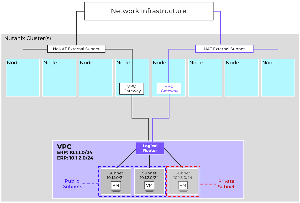 Example VPC with both private subnets for backend workloads and a public subnet for frontend services
During creation, a VPC can be marked as a Transit VPC. Transit VPCs extend the functionality of standard VPCs by enabling the creation of Overlay External Subnets which can be used to provide external connectivity to other standard VPCs. Overlay External Subnets are configured the same as VLAN-backed external subnets and provide the same functionality, ingress and egress for a VPC.
When configuring a NAT Overlay External Network, the NAT Network’s subnet should itself be considered a routable subnet by the Transit VPC, ensuring that external resources can reach the SNAT addresses or Floating IPs assigned out of the IP pool.
Routed Overlay External Networks operate as routing transit networks. These networks do not need to be externally reachable themselves, but merely act as a routed link between the Transit VPC and any connected VPCs. IP ranges such as the 100.64.0.0/10 Shared Address Space are suitable candidates for use with these networks.
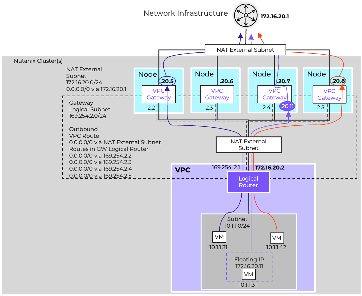
Flow Virtual Networking provides increased north/south bandwidth and improved fault tolerance via Gateway Scale-Out. With Gateway Scale-Out, up to four hosts can act as active gateways per VPC per external network; the default is two active gateway nodes per external network. If a VPC is connected to both a NAT and Routed external network, it can have multiple active gateways for each external network type, with different hosts selected for each external network.
Each gateway scaleout node is configured as an OVN redirect chassis, with outbound traffic being distributed amongst the gateways via ECMP. An internal gateway logical subnet in the 169.254.0.0/16 address space is created automatically to facilitate this. Overlay networks do not support Gateway Scale-out.
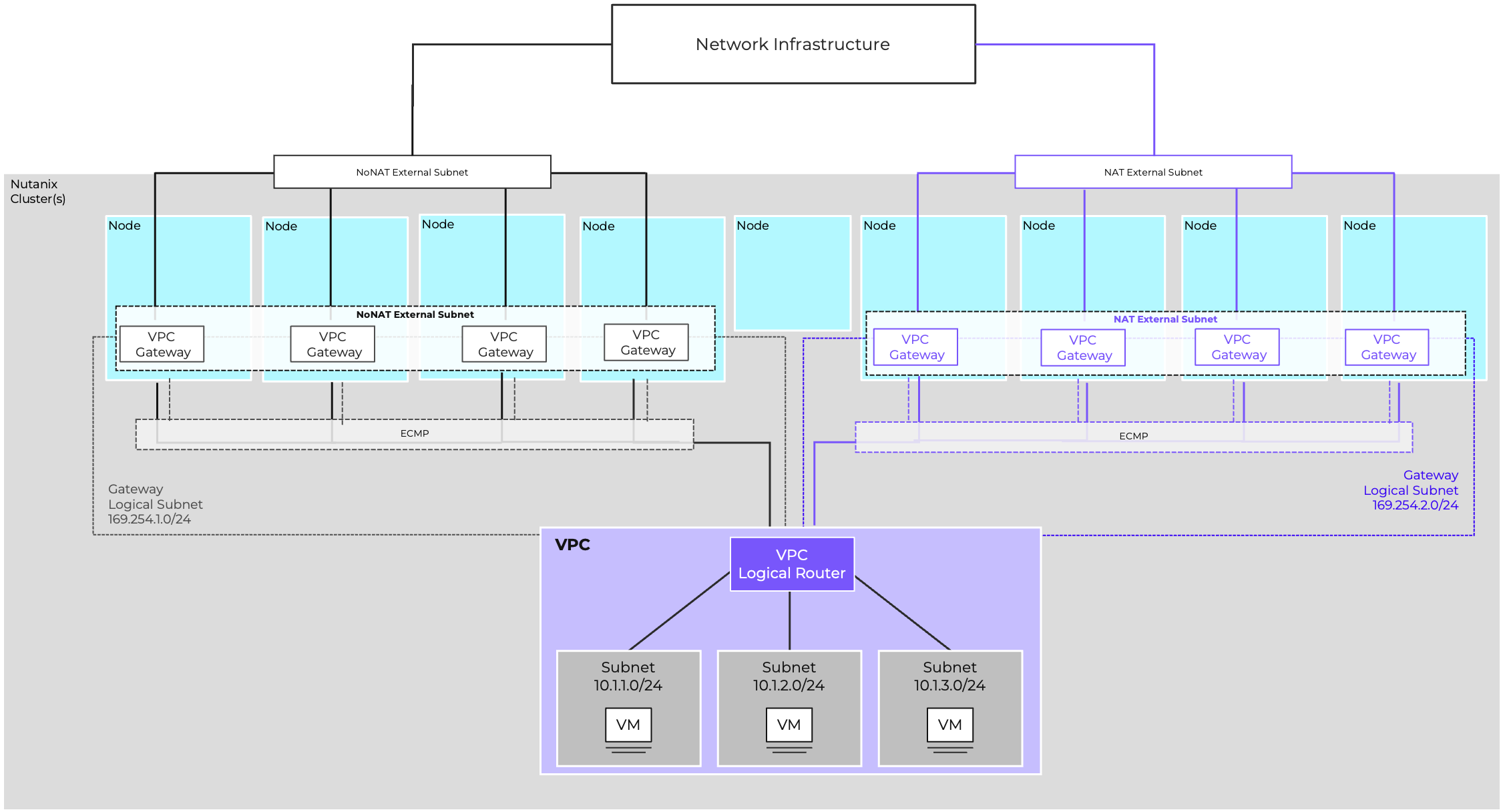
When utilizing a NoNat (Routed) External Network, the system allocates a Router IP from the external network’s IP Pool to each gateway node. Consequently, inbound traffic destined for any routable networks must be ECMP routed across all assigned router IPs.
For a NAT External Network, each gateway node receives a SNAT IP from the external network’s available IP pool. When outbound traffic leaves through a specific node, its outbound IP is translated to that gateway host’s SNAT IP. This ensures that the corresponding return traffic is correctly routed back to the same originating gateway host. This model increases throughput and reduces failure domain size.
Resiliency is achieved by distributing forwarding across hosts and designing gateways with redundancy. Administrators should consider failure domains such as rack-level outages and design gateway placement accordingly.
With the exception of single-node clusters, the Acropolis Leader will never host a gateway. If a node hosting a gateway fails, the Virtual Private Cloud (VPC) immediately stops using that failed gateway.
Traffic is maintained by the remaining active gateways.
The failed gateway is moved to an active, non-failed node.
If all active nodes are already hosting a gateway, one node will temporarily host two gateways, and traffic will be balanced equally between them.
The maximum number of active gateway nodes is n-1 of the total cluster size because of the Acropolis Leader, with a maximum of 4 per VPC. For example:
Even though FVN distributes forwarding tasks across several hosts, a gateway’s throughput capacity is limited by the capacity of the physical host. Therefore, proper planning is essential. This involves sizing the gateway host for the expected bandwidth needs, closely monitoring usage, and scaling out the gateway infrastructure as capacity thresholds are approached.
Connections are round-robin assigned to gateways based on the NATed IP address. This assignment persists until the gateway becomes unavailable. SNAT and Floating IP connections are pinned in this fashion.
Flow supports multiple approaches to route advertisement:
Routing boundaries define how far connectivity extends. For example, private subnets may only route within a VPC, while public or NoNAT subnets extend into external networks.
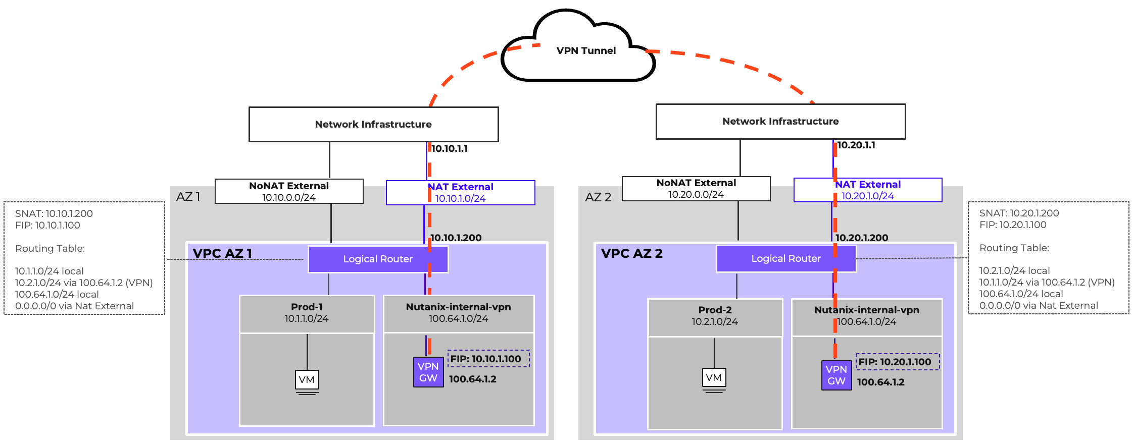
The VPN Gateway enables secure IPsec tunnels between Nutanix clusters or between a cluster and external sites. It provides encrypted connectivity for hybrid cloud designs and supports both policy-based and route-based configurations.
The VTEP Gateway allows Layer 2 extension of overlay subnets into external environments. This is useful when workloads must retain their IP addresses during migration or when applications rely on L2 adjacency.
While powerful, subnet extension should be used selectively, as it increases operational complexity and can create spanning domains.
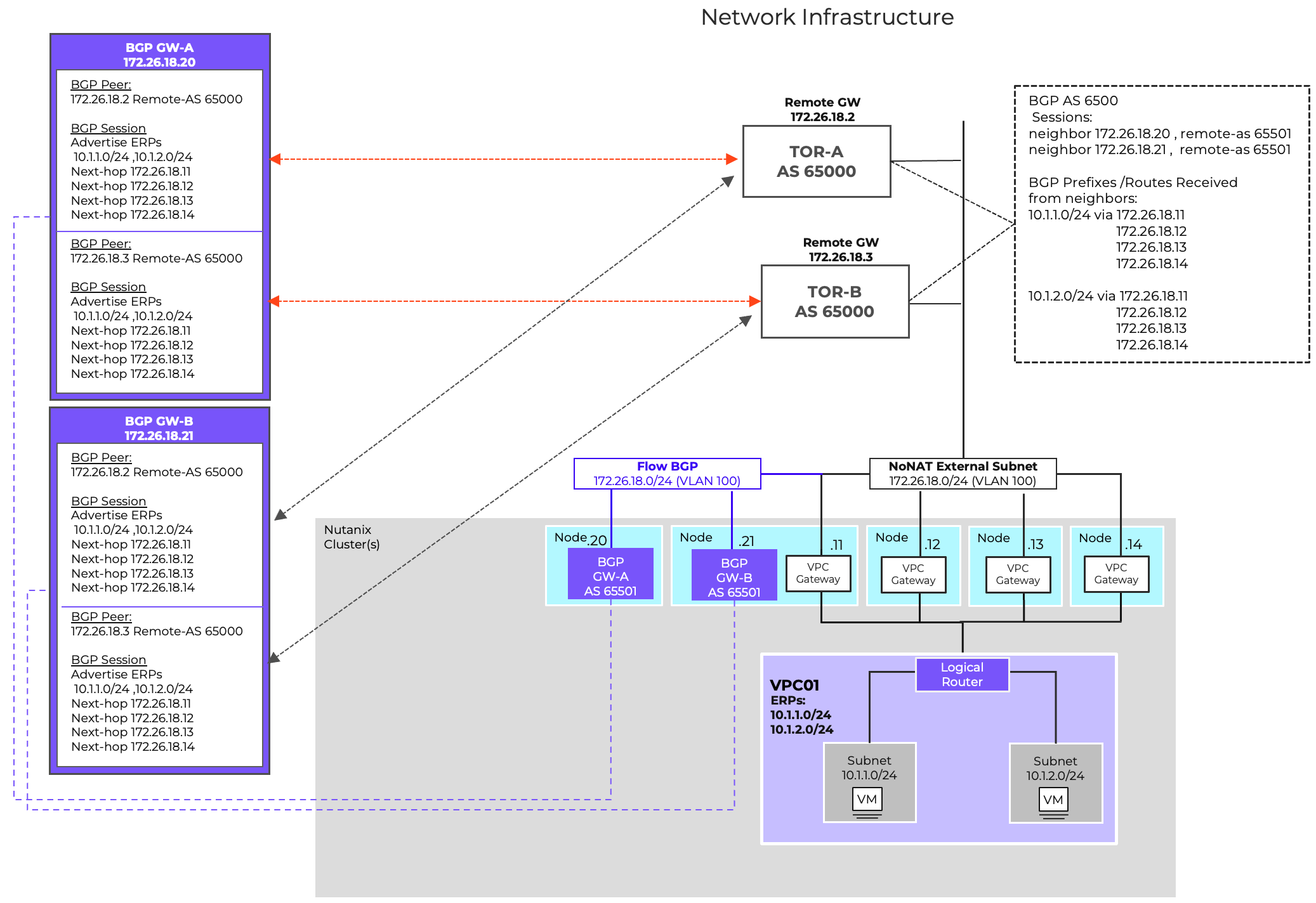
The BGP Gateway is essential when workloads need direct IP reachability without translation. It supports integration with existing enterprise routing domains, hybrid cloud connections, and scalable inter-VPC routing.
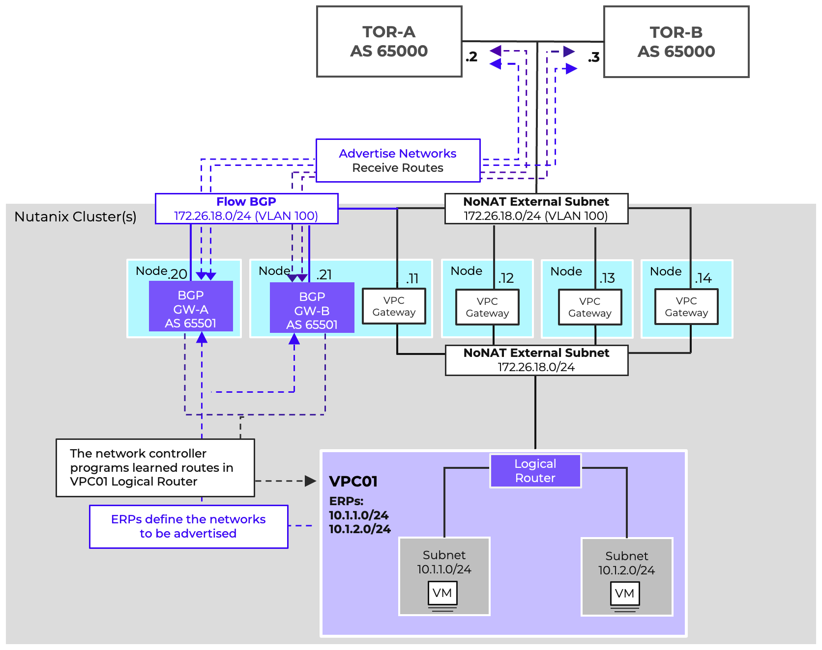
The BGP Gateway operates as a control-plane participant, advertising overlay prefixes and receiving external routes. The BGP Gateway dynamically advertises routes to overlay networks, known as an Externally Routable Prefix (ERP), to network infrastructure routers. The gateway also learns external routes from the infrastructure to distribute them into VPCs. This enables scalable, automated connectivity without relying on static routes.
While the BGP Gateway operates as a control-plane to the assigned VPC, the actual forwarding is still performed by the AHV hosts, ensuring distributed performance. The BGP gateway’s function is similar to that of a route server; the gateway is not in the data path.
BGP peers can be placed on VLAN-backed subnets for integration with physical routers, or on overlay subnets for virtual-only designs. This flexibility allows enterprises to choose the model that best fits their topology.
Floating IPs can be used at the gateway level to provide external reachability and redundancy. Design considerations include ensuring unique IP pools, aligning with underlay addressing, and planning for failover scenarios. Deploying a BGP gateway on a VPC overlay network requires the use of floating IPs. This deployment method does not support the use of MD5 authentication for BGP relationships, therefore it is not the preferred type of deployment.
For optimal BGP gateway deployment, it is a best practice to utilize a VLAN-backed network. This setup eliminates the need for Network Address Translation (NAT) and Floating IPs while simultaneously enabling MD5 authentication. To ensure high availability and redundancy for this essential routing component, deploy two BGP gateways per Virtual Private Cloud (VPC).
One BGP service IP per VPC Router (scaled-out gateway) IP is allocated on the NoNAT External Network. Each service IP advertises the VPC’s ERPs with a virtual gateway router IP as next hop. Up to 250 routes can be learned per session. Remote gateways must advertise their next-hop on the NoNAT External Subnet.
When deploying multiple BGP Gateways to service a VPC, anti-affinity between gateways should be set to avoid both gateways from residing on the same AHV host.
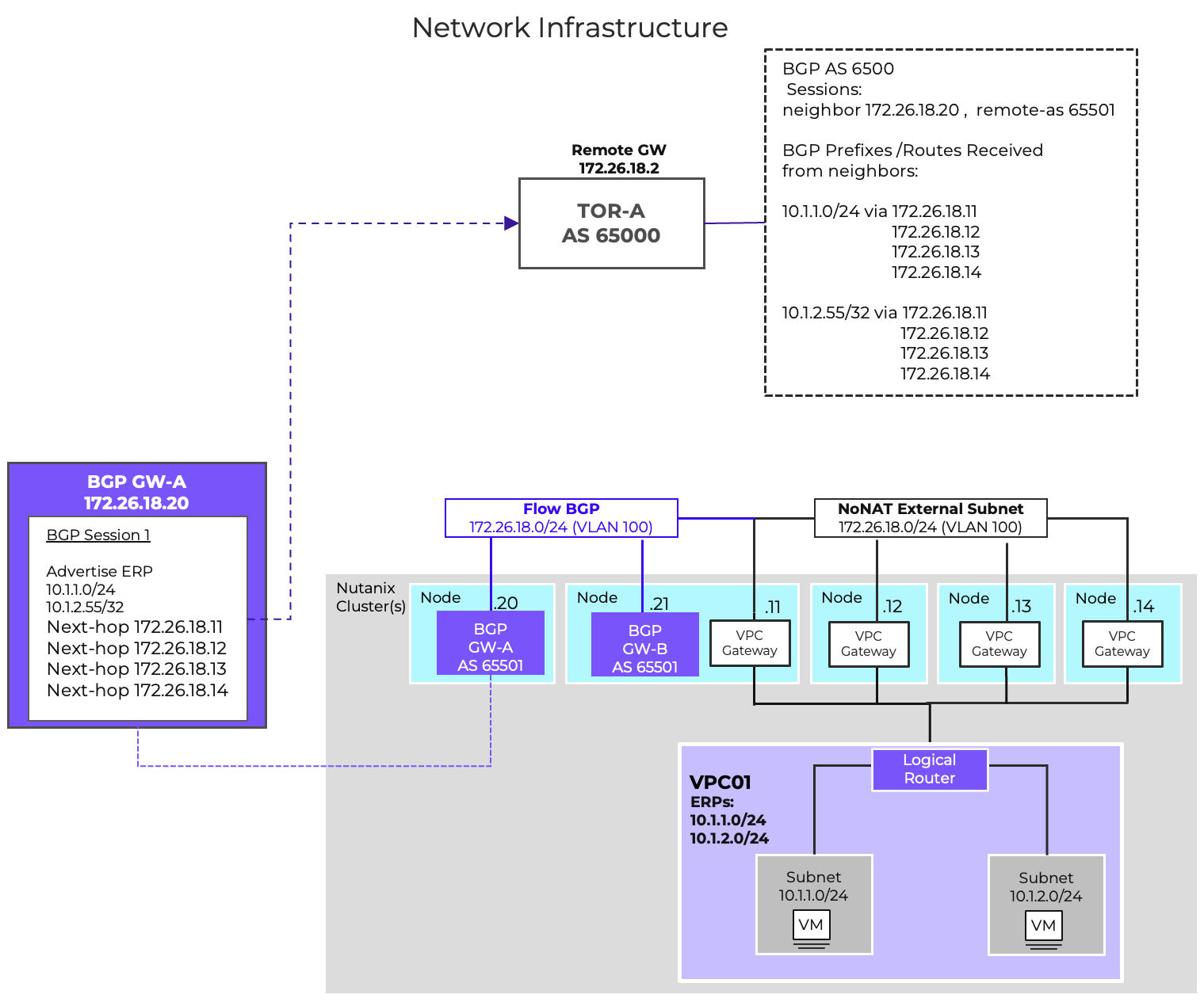
The BGP Gateway offers flexible network advertisement, supporting prefix lengths from /1 to /32. This support enables precise configurations that align with your existing network topology and policy requirements.
This capability is useful for scenarios like advertising a specific application or function within a VPC to the wider infrastructure, while simultaneously ensuring that other applications or VMs in the same VPC remain isolated and inaccessible.
Additionally, this granularity isn’t limited to BGP. You can leverage this feature to control which specific addresses or subsets of IPs are known and accessible via a Transit VPC.
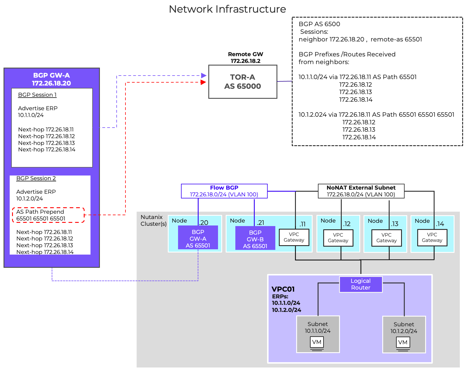
Within the BGP protocol, AS Path length is part of BGP Path selection criteria. The path with the shortest AS Path length is often the best path and is installed in the routing table.
With AS-Path Prepending we can influence routing by artificially increasing the length of a path. This is done by adding your Autonomous System Number (ASN) multiple times to the beginning of the AS path attribute.
Because this increases the AS Path Length, this route would be less preferred.
This can be used to help steer inbound traffic to a VPC-based externally routable prefix through specific networks, routers or ports.
AS-Path Prepending is also very useful for Active/Backup deployments across availability zones. The VPCs in the primary AZ can advertise their networks without AS Path prepending, making them the preferred path to the ERPs.
The DR AZ would also advertise these ERPs to the infrastructure, but will use AS PATH prepending for these network advertisements, making the paths from the DR AZ less preferred. If there was a failure of primary AZ causing the preferred path to be removed from the routing table, the secondary path via AZ2 would become the preferred path. This would allow traffic to continue to flow into the environment without any routing intervention or changes.
AS Path Prepend is configurable per BGP session.
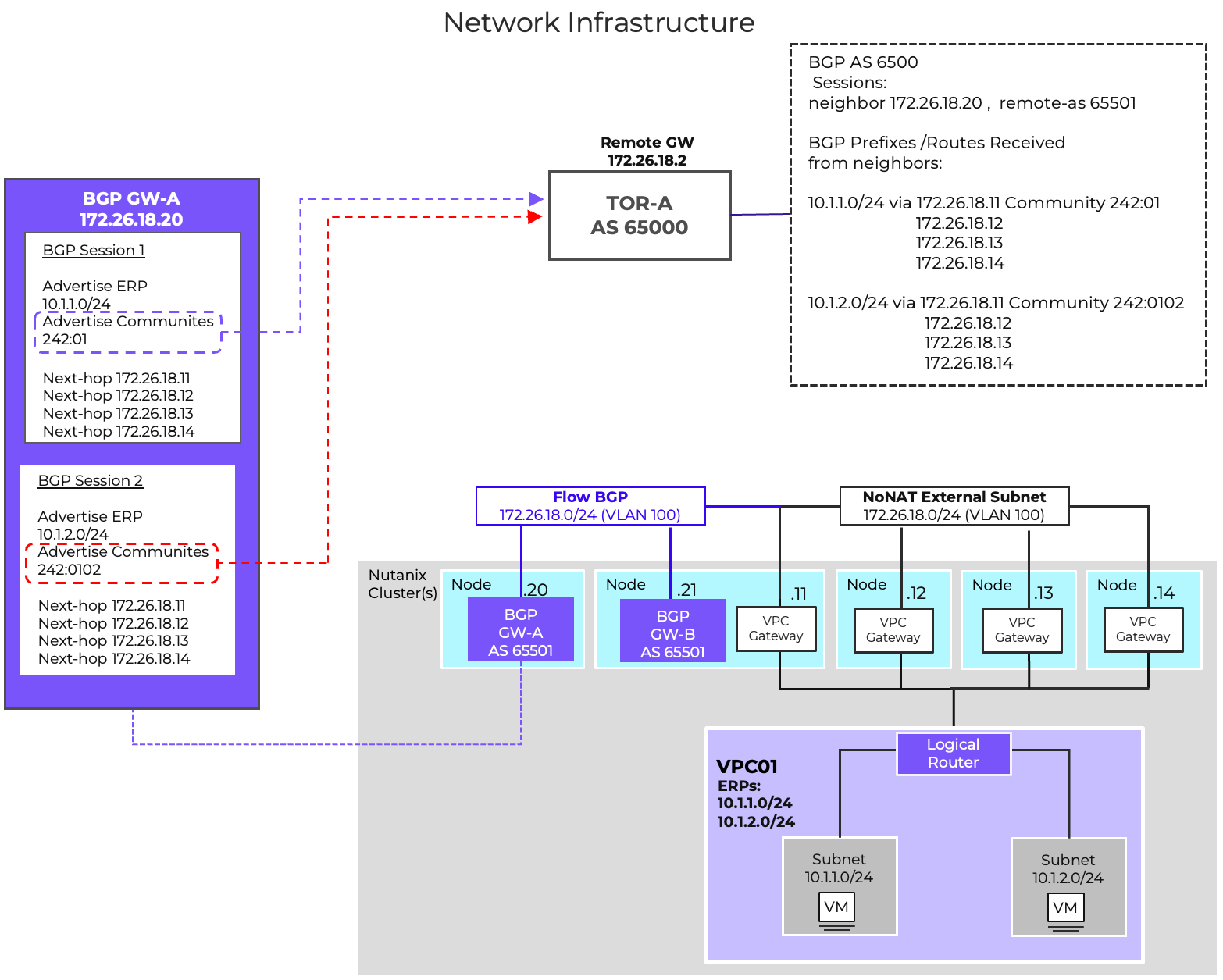
BGP Communities are tags that get attached to advertised routes, allowing the receiving peer to apply routing policies based on the value of the tags. These policies could be used for a lot of different scenarios like directing traffic to a specific VRF, or influencing how routes are redistributed across the network . BGP Communities can also be used as a method to identify routes coming from specific environments.
In Flow Virtual Networking, BGP Communities are only for outbound route advertisements. The FVN BGP gateway ignores any community tag received. The gateway does not take any action on received BGP communities. BGP Communities are configurable per BGP session.
BGP Additional Paths (Add-Path), standardized in 2016 via RFC 7911, is a BGP capability that addresses the default limitation of advertising only the single best path for a prefix. This enhancement allows a router to advertise multiple paths for the same prefix, significantly improving path diversity, reducing network convergence time, and streamlining configuration.
With Add-Path, multiple paths can be advertised through a single BGP peering session. This feature removes the necessity of creating separate BGP sessions for each VPC external network gateway, thereby reducing the total number of BGP sessions required per VPC. This protocol enhancement provides better scalability and operational simplicity.
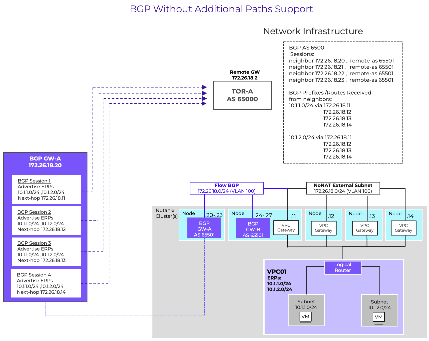
To utilize this feature, the capability must be supported and enabled on both the VPC BGP Gateways and the receiving neighbors (network infrastructure).
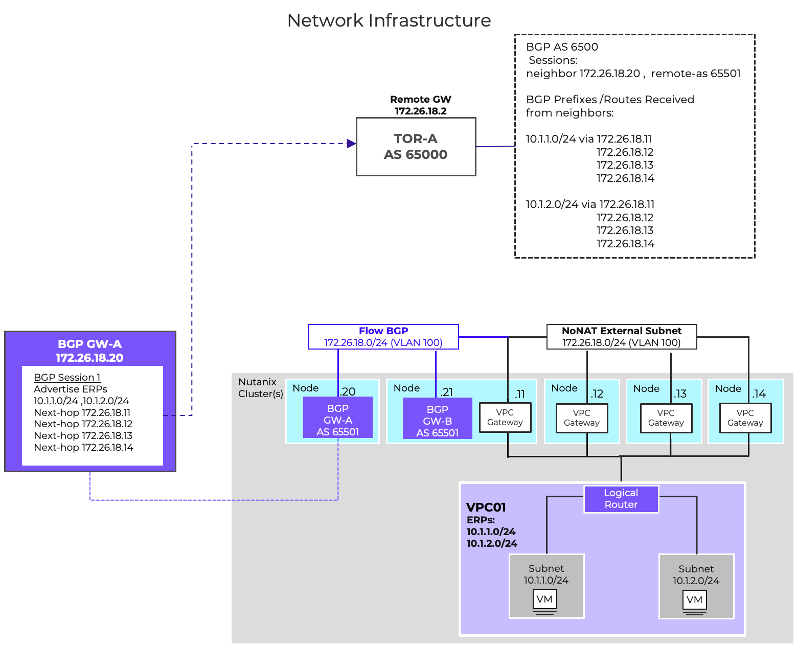
It is possible to deploy BGP gateways without Additional Paths support. This can be the case if the network infrastructure does not support the Add-Paths capability. In that design, a dedicated BGP sessions for every VPC external network gateway is required. With external gateway scale out, that could be up to 4 sessions per ERP per gateway.
Load balancers have been an important part of the data center infrastructure for a long time. Organizations have deployed load balancers to scale resources, improve reliability, eliminate single points of failure and help prevent overloading of servers.
The FVN Load Balancer, an integral component of Flow Virtual Networking (FVN), delivers distributed load balancing for data traffic. Its implementation scales linearly with the number of hosts in the cluster, eliminating single bottlenecks and allowing capacity to expand automatically as the environment grows. This native Layer 4 load balancing capability simplifies client traffic management by enabling the creation of rules directly within the Virtual Private Cloud (VPC), thereby ensuring high availability without the need for external appliances.
Session
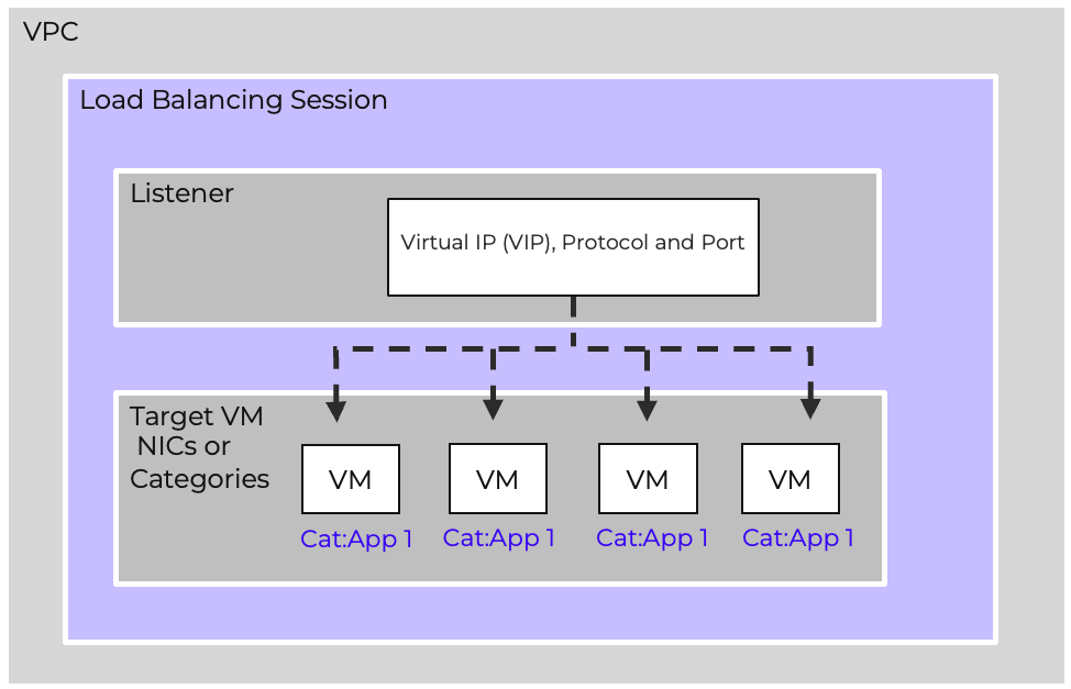
A Load Balancer session is deployed in a VPC. The session defines what protocol and port is being listened for, and where the traffic is balanced to.
Listener
The Listener is the front end of the load balancer, clients connect to the listener. The Listener is made up of a virtual IP address (VIP) and the port and protocol being balanced. The virtual IP is selected from the VPC overlay subnet.
Target
The load balancer distributes traffic to specific targets for a session. These targets can be either VM NICs or Categories that have been assigned to the VMs being load balanced.
Using categories for targets makes adding and removing target VMs simple and automatic.
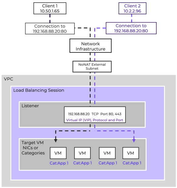
The service supports TCP and UDP workloads, handling both internal service distribution and external client access. Load balancing can be applied to frontend services exposed to external networks or to backend tiers requiring internal balancing.
The load balancer continuously probes backend members to ensure availability. The health check probes are sent to the ports defined in the target VM configuration. By default, these checks are sent every 5 seconds. A health check will timeout after 2 seconds if no response is received. A target is marked unhealthy after 3 consecutive failed checks. Targets marked unhealthy are automatically removed from rotation and will not receive traffic distributed from the listener until the target is marked healthy again. A target is marked healthy after 3 successful health check probes.
Load-balanced services can be exposed externally using floating IPs. This enables simple integration with NAT external subnets and ensures resilience for public-facing workloads.
The Nutanix LB is ideal for most common application workloads. For advanced use cases requiring deep L7 inspection, SSL offload, or global server load balancing, third-party ADCs can be integrated.
Subnet Extensions are a powerful feature of Flow Virtual Networking. VTEP Gateways use VXLAN to enable Subnets to participate in layer-2 bridging across layer-3 boundaries This can greatly simplify migrations by removing network-based constraints from scheduling. Similarly, Subnet Extensions add substantial flexibility to Disaster Recovery planning, enabling easier DR testing and partial subnet failovers by enabling IP mobility across availability zones. They also enable integration of physical infrastructure into a Virtual Private Cloud, meaning legacy workloads don’t need to be a hindrance to adoption of software defined networks.
However, it is vital that Subnet Extensions be used judiciously, ensuring that routing design and physical connectivity are considered to avoid undesirable asymmetric traffic. The standalone nature of VTEP Gateways also is a significant consideration before utilizing Subnet Extensions for any mission-critical applications. This section will discuss the design and functionality of VTEP gateways, as well as considerations for the most common use cases for Subnet Extensions.
VTEP Gateways are deployed as VMs running an instance of VyOS and acting as a virtual router. They can be deployed on either VLAN-backed Subnets or within a VPC. When deployed on a VLAN-backed Subnet, they are able to extend other VLAN-backed subnets. When deployed in a VPC, they are able to extend other subnets within the VPC.
VTEP Gateways use VXLAN, which is a Network Encapsulation standard similar to Geneve. VXLAN is commonly available across a variety of platforms, including virtual and physical network infrastructure, making it ideal for ensuring compatibility with as many external platforms as possible.
VTEP Gateways have a Service Interface, which is the first vNIC and is used for management traffic as well as acting as the VXLAN TEP. This initial vNIC is the eth0 interface for the VM. This service interface must be reachable via Prism Central via ping and TCP-8888 for monitoring and configuration. Additionally, the service interface must be able to reach a user-provided NTP server. If the configured NTP server is an FQDN address, the network gateway must also be able to reach a configured DNS server via the service interface.
Each Subnet Extension results in the addition of a vNIC and thus an additional eth interface. Additionally, a vxlan logical interface is created to manage the encapsulation and decapsulation of traffic for the extension. Finally a bridge interface is created to connect the eth interface to the vxlan interface. A listener IP for the extended subnet is allocated and assigned to the bridge interface. These interfaces are numbered, with the first subnet extension on a particular VTEP Gateway using eth1, br1, vxlan1, the second using eth2, br2, vxlan2, and so on. The following diagram shows a VTEP GW that is providing Subnet Extension functionality for two subnets.
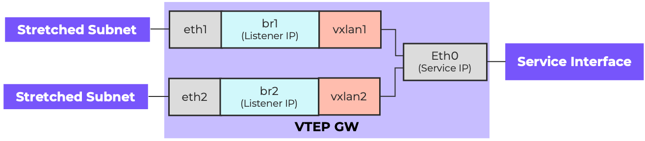 Anatomy of a VTEP Gateway
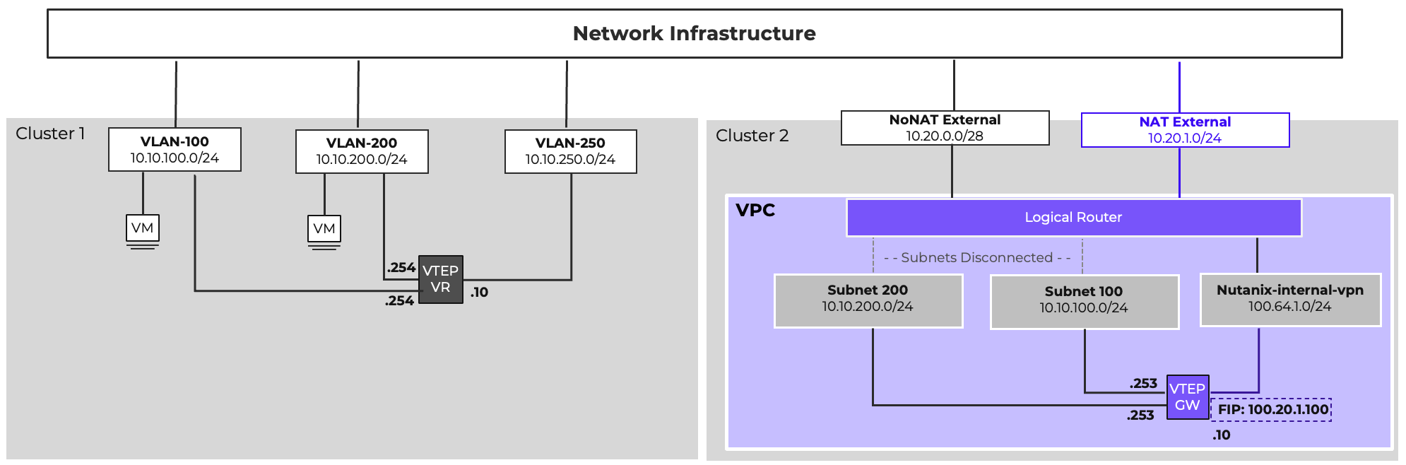
When any Network Gateway is deployed within a VPC, a service Subnet called Nutanix-internal-vpn is instantiated, using 100.64.1.0/24 for addressing. This subnet is used for the Service Interface. As the 100.64.1.0/24 address space would be used across multiple VPCs, a NAT External Network & a Floating IP are required. Additionally, if the default route for the VPC is a routed external network, a network policy must be configured to forward traffic from the 100.64.1.0/24 with an external destination to the NAT External Network gateway.
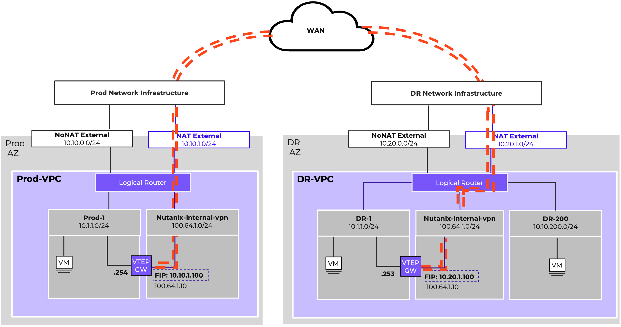
The above diagram shows an example of how subnet extensions can be used to support disaster recovery operations. In this example, the subnet extension’s purpose is to facilitate disaster recovery testing operations. By extending the subnet between sites, DR tests can be conducted by failing a subset of VMs over to the DR side. They are able to maintain their own IP address. Network policies can be configured on the DR-VPC to cause north/south traffic for the failed-over VMs back across the subnet extension. This allows for a DR test to be conducted without having to change IPs during the test, and without having to make any changes on the physical network infrastructure to support the test.
It’s important to understand, in this design, the Subnet Extension exists solely to simplify testing. During an actual DR event, the Subnet Extension is most likely no longer functional, as the production side would be down. When VMs are failed over, additional network configuration is likely required to allow the subnet to egress out of the DR datacenter. The network policies configured to support egress redirection should be removed, and routing configurations may need to be adjusted. The required operations vary based on physical network design and specific VPC configuration.
It is recommended that vital infrastructure services, such as domain controllers, have an always-on instance deployed to support DR, preventing any delays in return to operation while waiting for these services to spin up. These resources should not be deployed in a stretched subnet. It is recommended that they be deployed in a subnet specific to the DR environment, and this is shown as DR-200 in the above diagram.
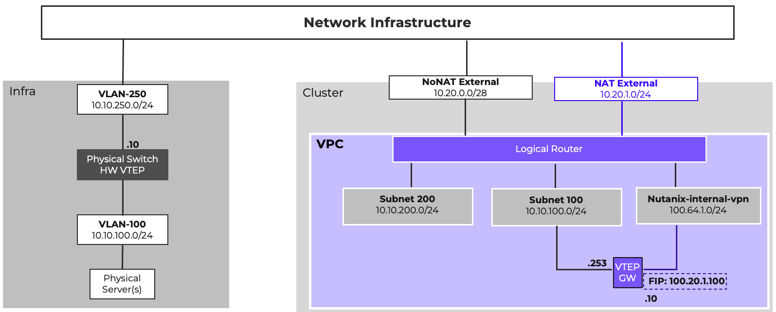
Subnet Extensions are regularly used to facilitate migrations into Flow Virtual Networking, allowing VMs to be migrated in phases without requiring IP changes. The above diagram shows an example of how this can be achieved. In the diagram, VMs on VLAN-100 and VLAN-200 are to be moved into a VPC on a new Nutanix cluster. Subnets can be created in the new VPC with matching addressing, and a VTEP Gateway deployed.
A software VTEP can be deployed on the source side. VyOS Virtual Routers are an excellent option for this, since Nutanix Network Gateways are built on the VyOS platform themselves. The VTEPs on the source side will need to be manually configured in a manner similar to the Nutanix VTEP Gateway as shown above. The sample configuration below would configure a VyOS virtual router to match the picture above.
set interfaces ethernet eth0 address 10.10.150.250/24
set protocols static route 0.0.0.0/0 next-hop 10.10.150.1
set service ssh
set interfaces bridge br1 address 10.10.100.254/24
set interfaces bridge br1 aging '300'
set interfaces bridge br1 member interface eth1
set interfaces bridge br1 member interface vxlan1
set interfaces bridge br1 mtu '1392'
set interfaces vxlan vxlan1 ipv6 address no-default-link-local
set interfaces vxlan vxlan1 mtu '1392'
set interfaces vxlan vxlan1 port 4789
set interfaces vxlan vxlan1 remote 10.20.1.100
set interfaces vxlan vxlan1 source-address 10.10.250.10
set interfaces vxlan vxlan1 vni 100
set interfaces bridge br2 address 10.10.200.254/24
set interfaces bridge br2 aging '300'
set interfaces bridge br2 member interface eth2
set interfaces bridge br2 member interface vxlan2
set interfaces bridge br2 mtu '1392'
set interfaces vxlan vxlan2 ipv6 address no-default-link-local
set interfaces vxlan vxlan2 mtu '1392'
set interfaces vxlan vxlan2 port 4789
set interfaces vxlan vxlan2 remote 10.20.1.100
set interfaces vxlan vxlan2 source-address 10.10.250.10
set interfaces vxlan vxlan2 vni 200
commit
save
With a remote VTEP configured, Subnet Extensions can be built. Then, the subnets can be set to a disconnected state via atlas_cli, the command line interface in Prism Central for managing Flow Virtual Networking. This causes both subnets to use the existing network infrastructure and default gateway for both north/south and east/west traffic.
Once a Subnet’s migration has proceeded to the point where most of the traffic is now originating from the Nutanix side, the subnet can be reconnected to the VPC Logical Router, and the original network’s default gateway can be shut down. That subnet can then be directed to the Nutanix VPC, either by static routing or by advertising the subnet via BGP. Once all subnets are migrated, the subnet extensions and VTEP gateway can be removed.
In certain cases, egress traffic redirected across a subnet extension may fail due to VPC or physical network design. If this occurs, please contact support and reference KB-19698 to address this issue.
Subnet extensions can be built to hardware VTEPs as well, and many modern switches can be configured to act as a VTEP. With this configuration, legacy physical gear can live within a VPC if layer-2 adjacency to other VMs is a requirement.
Subnet Extensions, when used appropriately are an excellent tool to extend the functionality of Flow Virtual Networking. However, they must be used carefully. Layer 2 and Layer 3 operate in tandem. Extending a subnet without carefully considering traffic routing and possible asymmetric traffic patterns can result in unexpected and undesirable behavior.
Throughput considerations and scale limitations are also important. A VTEP Gateway can reasonably provide 3.5Gbps of throughput. Each Subnet extended through the same gateway shares that throughput, and Prism Central can manage a finite number of VTEP Gateways (see the Configuration Maximums section.)
Finally, be aware that VTEP Gateways are VMs, and are not deployed in a highly available manner. That is to say, if the host that a VTEP Gateway is on fails, any traffic depending on a Subnet Extension will be disrupted until the VTEP Gateway reboots on another host. Because of this, limit the reliance of critical or production traffic on Subnet Extensions as much as possible. When using Subnet Extensions for migrations, plan your migrations to minimize the duration that the extension is required as much as possible. Ensure that you consider the throughput limitations and scale limits when planning Extensions and VTEP Gateways. When extending multiple subnets, consider dedicated VTEP Gateways for higher utilization networks, while pairing up lower utilization networks if necessary.
Prism Central should be deployed in a 3-node scale-out configuration for the highest management plane availability. Deploy within the same Availability Zone/datacenter as managed clusters.
The integrated Network Controller is suitable for most scenarios and is recommended as the default option, as it supports all features of Flow Virtual Networking & Flow Network Security. When deploying the integrated Network Controller in a production environment, Prism Central must be scaled out. Failing to do so will cause Prism Central maintenance operations, including upgrades and reboots caused by host failure, to induce network disruptions. Deploying the integrated Network Controller will cause the following resource adjustments for Prism Central.
| PC Size | RAM | vCPU |
|---|---|---|
| Small | +3 GB per VM | +2 vCPU per VM |
| Large | +4 GB per VM | +3 vCPU per VM |
| X-Large | No additional resources needed, Network Controller included by default |
The Standalone Flow Controller can be deployed when organizational requirements call for disaggregation of the management and control planes. The Standalone Flow Controller can also be deployed in production environments where Prism Central will not be scaled out. Similar to Prism Central, the Flow Controller deployment has three sizes consuming the following resources:
| Size | RAM | vCPU |
|---|---|---|
| Small | 56 GB | 28 vCPU |
| Large | 68 GB | 40 vCPU |
| X-Large | 90 GB | 52 vCPU |
The following features are currently not supported by the Standalone Flow Controller:
Geneve encapsulation incurs an overhead cost of 58 bytes on top of standard ethernet framing. To allow for this without a loss of performance, all physical switches used for host to host communication should ideally be configured to support an MTU of 9000 bytes if possible, and 1558 at minimum. Additionally, the virtual switch configured for VPC east/west traffic (vs0 by default) should be configured to match. By default, DHCP will advertise an MTU of 1442 to VPC guest VMs regardless of the MTU set on the VPC E/W virtual switch. It is possible to increase the advertised MTU on a per-subnet basis via atlas_cli in Prism Central. Alternatively, the guest OS MTU can be manually increased to take advantage of a higher available MTU if desired.
Do not attempt to modify the MTU of Prism Central VMs or CVMs unless instructed by Nutanix support.
In cases where the physical and virtual switch MTU cannot be increased, the DHCP MTU advertisement will prevent fragmentation for VMs receiving their IP assignment via DHCP. Not all guest operating systems honor DHCP MTU advertisement. In those cases, if the physical and virtual switch MTU are unable to be increased, ensure that the guest OS MTU configuration is manually set to the value in the table below dependent on the features in use:
| Feature | MTU (Overhead Calculation) |
|---|---|
| VPC | 1442 (1500 - 58 Geneve) |
| VPC + Subnet Extension | 1392 (1500 - 58 Geneve - 50 VXLAN) |
| VPC + VPN | 1356 (1500 - 58 Geneve - 86 IPSec) |
| VPC + Subnet Extension + VPN | 1306 (1500 - 58 Geneve - 50 VXLAN - 86 IPSec) |
Prism Central sizing is primarily driven by the number of VMs in the environment. However, Flow Virtual Networking does have additional configuration maximums that might drive a larger Prism Central size than that driven by VM count alone. These include, but are not limited to, number of VPCs, Subnets, Network Gateways, BGP Sessions, and VPN Sessions. Please refer to the following pages on the Nutanix Support Portal for the full list of configuration maximums:
Configuration Maximums for the integrated Network Controller 7.0
Required connectivity between Prism Central, AHV hosts, CVMs, Network Gateways, and other infrastructure components is essential for proper functionality. The specific connectivity required for Flow Virtual Networking is documented in the Ports and Protocols section of the Nutanix Support Portal.
There are two built-in RBAC roles specific to Flow Virtual Networking. The VPC Admin role is geared towards allowing operations exclusively for VPCs and Overlay Subnets, and consists of 83 operations across 21 entity types. VPC Admins are able to manage VPCs, overlay subnets, Floating IPs, PBR policies, routing policies, LB sessions, network gateways, VPN connections, and BGP sessions.
The Network Infra Admin allows management of VLAN-backed networking and related components, and consists of 60 operations across 13 entities. Network Infra Admins can manage virtual switches, VLAN subnets, VLAN external subnets, network gateways, VPN connections, L2 extensions, and traffic mirroring.
Both roles can manage Network Gateways, VPN Connections, and Layer 2 Subnet Extensions. Overlay External Subnets and NIC Profiles require Super Admin or Prism Admin roles. Starting with AOS 7.0/pc.2024.3, entity types use updated filter attributes for more granular permissions.
In this section, we will explore a number of standard reference designs for Flow Virtual Networking on Nutanix Cloud Infrastructure 7.5. In all instances, the configuration assumes the following major versions:
Prism Central: 7.5.x
AHV: 11.x
AOS: 7.5.x
Network Controller: 7.0
In these designs, we are focusing mainly on the VPC design and configuration, and leaving the physical infrastructure abstract and simplified. These VPC architectures can be implemented as shown in most environments, requiring minimal adjustment depending on the physical topology. For example, a larger cluster that spans multiple leaf pairs in a spine & leaf architecture could have more complex requirements for providing external network connectivity than a smaller cluster connecting to a single access pair in a traditional collapsed core design. Such complexities, while a significant consideration, are outside the scope of this document. Functional variations between network vendors, including different models from the same vendor, preclude a definitive external networking design.
For details on physical host connectivity, refer to the Physical Networking Best Practices Guide on the Nutanix Support Portal. For more information on general AHV networking, including virtual switch configuration, refer to the AHV Networking Best Practices Guide on the Nutanix Support Portal.
In all design examples, Prism Central is deployed as a scale-out cluster on the Nutanix-Mgmt VLAN, and the Integrated Network Controller is deployed. All networking will use the standard vs0 virtual switch.
A single VPC with static routing is the most basic Flow Virtual Networking deployment. In this design, a 5-node AHV cluster running NCI 7.5 is installed, and all nodes are connected to the same pair of switches.
The following External Networks are configured:
| Name | Flow-Ext-NoNAT | Flow-Ext-NAT |
|---|---|---|
| VLAN ID | 200 | 201 |
| Virtual Switch | vs0 | vs0 |
| External Connectivity for VPCs | Enabled | Enabled |
| NAT | Disabled | Enabled |
| Network CIDR | 10.0.200.0/24 | 10.0.201.0/24 |
| Gateway | 10.0.200.1 | 10.0.201.1 |
| IP Pool | 10.0.200.10-10.0.200.19 | 10.0.200.10-10.0.200.250 |
A single VPC will be configured leveraging both of these external networks. It is preferred that the default route use the NoNAT external network. The NAT external network will be configured to allow for later assignment of Floating IPs as needed. The 10.10.0.0/16 address space has been allocated for use within the VPC, and does not overlap with anything external in our example. As such, the 10.10.0.0/16 IP space can be defined as externally routable. Modify this to suite your specific environment as needed. With the cluster containing five nodes, four nodes are available to act as gateway nodes. As such, for maximum north/south bandwidth, both external networks will be configured for 4 active gateway nodes. The following VPC configuration accomplishes this:
| Name | Prod-VPC |
|---|---|
| Transit VPC | No |
| Externally Routable IP Prefixes | 10.10.0.0/16 |
And the details of each External Subnet connected to the Prod-VPC follow:
| Name | Flow-Ext-NoNAT |
|---|---|
| Set this subnet as default next hop for outbound traffic. | Yes |
| Destination Prefixes | 0.0.0.0/0 |
| Router IP Assignment Mode | Custom Defined |
| Custom Router IP | 10.0.200.10, 10.0.200.11, 10.0.200.12, 10.0.200.13 |
| External Gateway Configuration: Number of Active Hosts | 4 |
| Name | Flow-Ext-NAT |
|---|---|
| Set this subnet as default next hop for outbound traffic. | No |
| Destination Prefixes | N/A |
| SNAT IP Assignment Mode | Custom Defined |
| Custom SNAT IP | 10.0.201.10, 10.0.201.11, 10.0.201.12, 10.0.201.13 |
| External Gateway Configuration: Number of Active Hosts | 4 |
This simple design leverages static routing. As such, the network infrastructure will need to be configured with static routes for the 10.10.0.0/16 IP block. To take advantage of gateway scale-out, a static route for the 10.10.0.0/16 destination should be configured with each Custom Router IP as the next hop.
Within the VPC, we are able to configure overlay subnets. Four example subnets are shown here, but this design allows full flexibility and usability of the 10.10.0.0/16 address space.
While static routing may be suitable for some deployments, many organizations require the flexibility of being able to allocate and utilize additional address spaces without requiring manual configuration of new routes on the physical network. The VPC design can be augmented with BGP to facilitate this.
For simplicity, we want to deploy the BGP gateways on the same VLAN as the VPC external network. As an External Network cannot be connected directly to a VM, we will create a non-external instance of VLAN200 called Flow-BGP. Configure this additional VLAN with External IPAM to avoid address conflicts. We will deploy two BGP gateways for high availability in Additional Paths mode to simplify configuration. The following Network Gateways will be configured:
| Gateway Name | BGP-GW-A | BGP-GW-B |
|---|---|---|
| Gateway Attachment | VLAN | VLAN |
| Subnet | Flow-BGP | Flow-BGP |
| DNS Configuration | Inherit from Cluster | Inherit from Cluster |
| NTP Configuration | Inherit from Cluster | Inherit from Cluster |
| Gateway Service | BGP | BGP |
| Serviced VPC | Prod-VPC | Prod-VPC |
| BGP Path Advertisement Configuration | Advertise Multiple Routes | Advertise Multiple Routes |
| Static IP Address | 10.0.200.20/24 | 10.0.200.21/24 |
| Default Gateway | 10.0.200.1 | 10.0.200.1 |
| eBGP ASN | 65001 | 65001 |
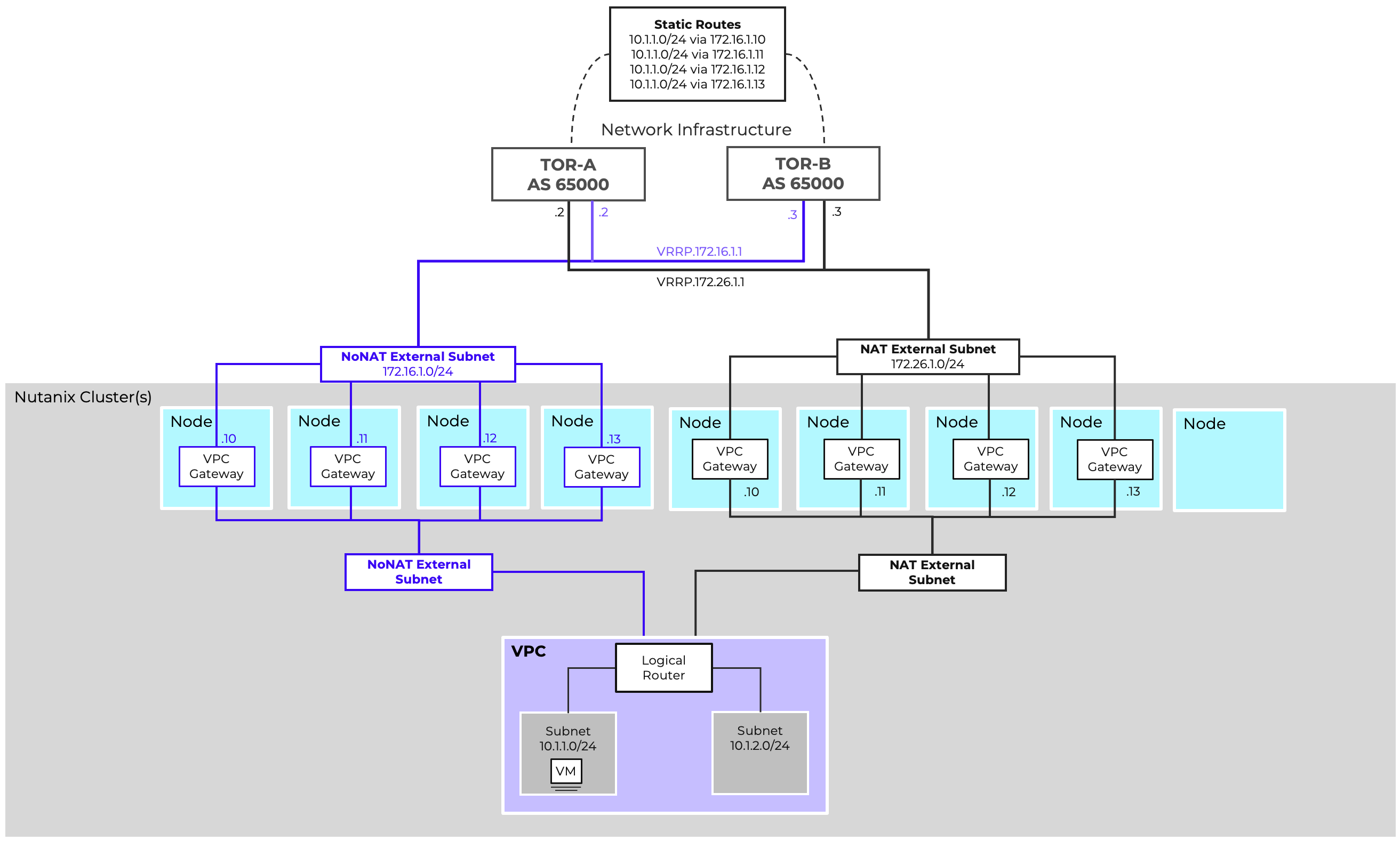
Each of the TOR switches will be configured as a remote gateway, and both BGP gateways will be peered to both TOR switches. This will enable the BGP gateways to advertise the configured Externally Routable IP Prefixes to both TORs with all four router IPs advertised as an eligible, installable path. The following Remote Gateways will be configured:
| Name | TOR-A | TOR-B |
|---|---|---|
| Gateway Service | BGP | BGP |
| Service IP Address | 10.0.200.2 | 10.0.200.3 |
| eBGP ASN | 65001 | 65001 |
The following BGP Sessions will be configured:
| Local Gateway | BGP-GW-A | BGP-GW-A | BGP-GW-B | BGP-GW-B |
|---|---|---|---|---|
| Remote Gateway | TOR-A | TOR-B | TOR-A | TOR-B |
| Session Name | GW-A-TOR-A | GW-A-TOR-B | GW-B-TOR-A | GW-B-TOR-B |
| Advertised Externally Routable Prefixes | All in VPC | All in VPC | All in VPC | All in VPC |
| Dynamic Route Priority | Automatically Set | Automatically Set | Automatically Set | Automatically Set |
| Password | None | None | None | None |
| AS Path Prepend | None | None | None | None |
| Advertised Communities | None | None | None | None |
Finally, we will want to configure the TORs to advertise a default route with the VRRP virtual IP as the next hop instead of their real IP. This is generally accomplished with a route map on most network infrastructure. When configuring BGP, it is no longer necessary to manually configure the Flow-Ext-NoNAT as the default next hop for the VPC.
With this added, new networks can be configured. Adding these addresses to the VPC’s Externally Routable IPs field will allow those addresses to be advertised to the physical network infrastructure.
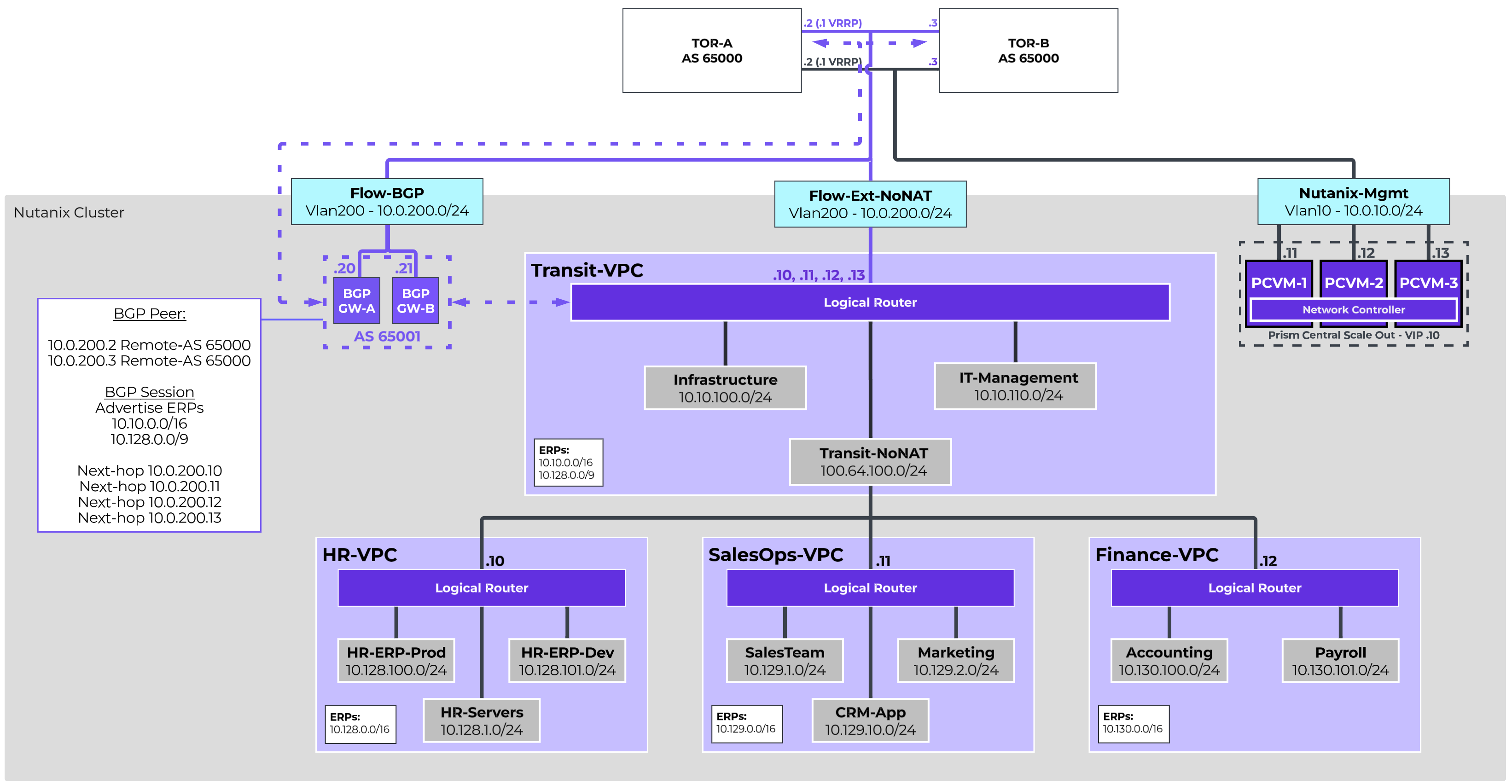
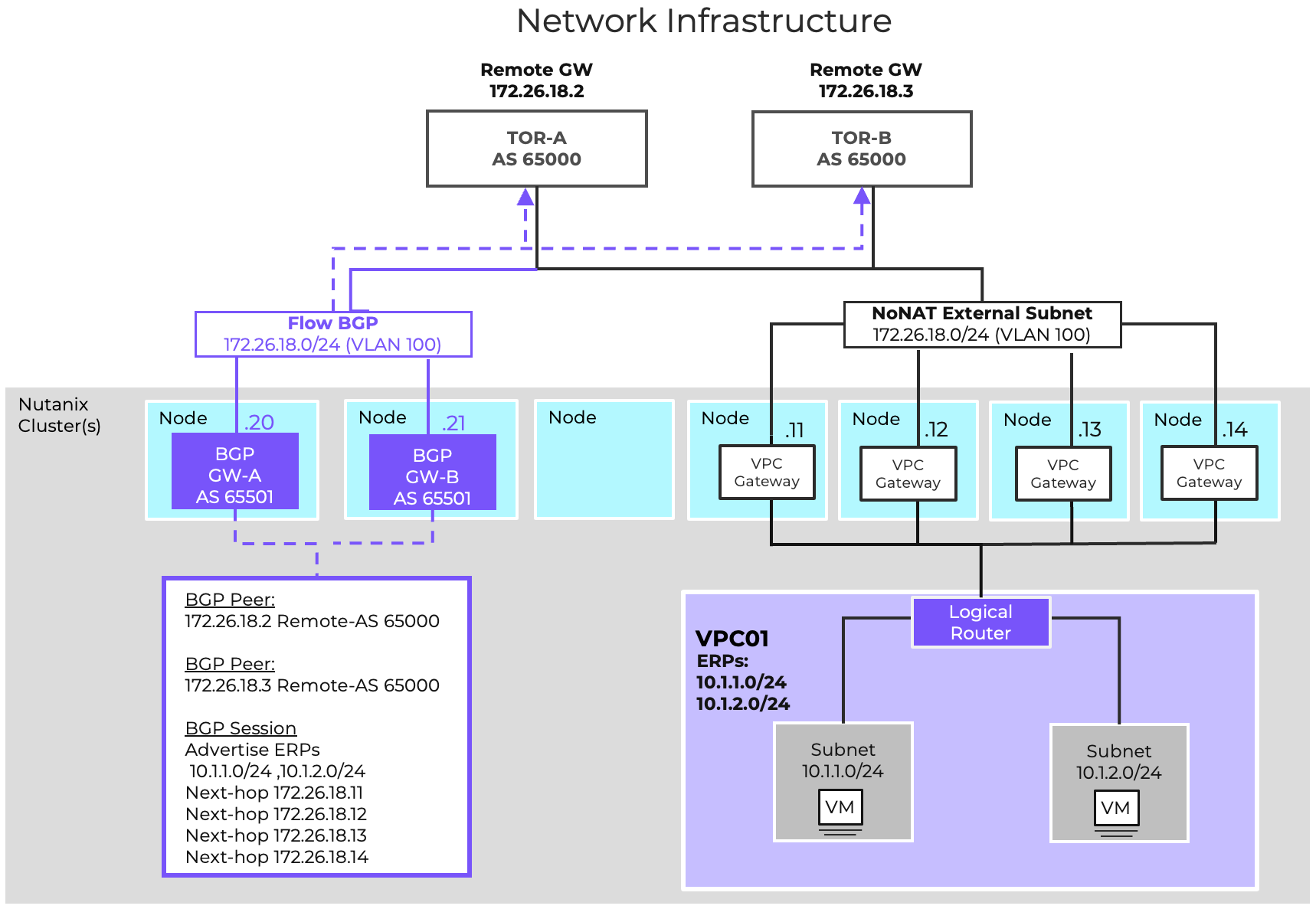
The Enterprise Transit VPC Design is a suitable starting point for larger organizations that want to provide dedicated network spaces for independent business units. This two-tier design utilizes a Transit VPC to provide centralized connectivity and services for multiple individually connected VPCs. In this design, a 10-node AHV cluster running NCI 7.5 is installed, and all nodes are connected to the same pair of switches.
All resources in the environment will be allocated unique private IPs and should be directly addressable, so a Routed/NoNAT External Network will be sufficient. The 10.10.0.0/16 subnet is allocated for shared resources. 10.128.0.0/9 has been allocated for individual business unit environments, and individual /16s will be allocated for individual BU VPCs. Additionally, the network team requires that dynamic routing be utilized across the infrastructure, so BGP Gateways will be deployed to provide dynamic routing. We will configure two Subnets for VLAN200. One will be configured as the Routed External Network, and the other will allow the BGP Gateways to reside on the same network segment. To that end, the following VLAN-Backed Networks are configured:
| Name | Flow-Ext-NoNAT | Flow-BGP |
|---|---|---|
| VLAN ID | 200 | 200 |
| Virtual Switch | vs0 | vs0 |
| External Connectivity for VPCs | Enabled | Disabled |
| NAT | Disabled | N/A |
| IPAM | Nutanix IPAM | External IPAM |
| Network CIDR | 10.0.200.0/24 | 10.0.200.0/24 |
| Gateway | 10.0.200.1 | 10.0.200.1 |
| IP Pool | 10.0.200.10-10.0.200.19 | N/A |
The Transit VPC will be configured leveraging the Flow-Ext-NoNAT as the only external network. There is no need to set the external network as the static default route as we will learn routing via BGP. The allocated address spaces will be configured as Externally Routable IP Prefixes.
| Name | Transit-VPC |
|---|---|
| Transit VPC | Yes |
| External Subnet: | Flow-Ext-NoNAT |
| Set this subnet as default next hop for outbound traffic | No |
| Destination Prefixes: | N/A |
| Router IP Assignment Mode: | Custom Defined Custom Router IP 10.0.200.10, 10.0.200.11, 10.0.200.12, 10.0.200.13 |
| External Gateway Configuration: Number of Active Hosts | 4 |
| Externally Routable IP Prefixes: | 10.10.0.0/16, 10.128.0.0/9 |
Like the basic VPC design, we want to deploy the BGP gateways on the same VLAN as the VPC external network. As an External Network cannot be connected directly to a VM, we will create a non-external instance of VLAN200 called Flow-BGP. Configure this additional VLAN with External IPAM to avoid address conflicts. We will deploy two BGP gateways for high availability in Additional Paths mode to simplify configuration. The following Network Gateways will be configured:
| Gateway Name | BGP-GW-A | BGP-GW-B |
|---|---|---|
| Gateway Attachment: | VLAN | VLAN |
| Subnet: | Flow-BGP | Flow-BGP |
| DNS Configuration: | Inherit from Cluster | Inherit from Cluster |
| NTP Configuration: | Inherit from Cluster | Inherit from Cluster |
| Gateway Service: | BGP | BGP |
| Serviced VPC: | Transit-VPC | Transit-VPC |
| BGP Path Advertisement Configuration: | Advertise Multiple Routes | Advertise Multiple Routes |
| Static IP Address: | 10.0.200.20/24 | 10.0.200.21/24 |
| Default Gateway: | 10.0.200.1 | 10.0.200.1 |
| eBGP ASN: | 65001 | 65001 |
Each of the TOR switches will be configured as a remote gateway, and both BGP gateways will be peered to both TOR switches. This will enable the BGP gateways to advertise the configured Externally Routable IP Prefixes to both TORs with all four router IPs advertised as an eligible, installable path. The following Remote Gateways will be configured:
| Name | TOR-A | TOR-B |
|---|---|---|
| Gateway Service: | BGP | BGP |
| Service IP Address: | 10.0.200.2 | 10.0.200.3 |
| eBGP ASN: | 65000 | 65000 |
The following BGP Sessions will be configured:
| Local Gateway | BGP-GW-A | BGP-GW-B | ||
|---|---|---|---|---|
| Remote Gateway: | TOR-A | TOR-B | TOR-A | TOR-B |
| Session Name: | GW-A-TOR-A | GW-A-TOR-B | GW-B-TOR-A | GW-B-TOR-B |
| Advertised Externally Routable Prefixes: | All in VPC | All in VPC | All in VPC | All in VPC |
| Dynamic Route Priority: | Automatically Set | Automatically Set | Automatically Set | Automatically Set |
| Password: | None | None | None | None |
| AS Path Prepend: | None | None | None | None |
| Advertised Communities: | None | None | None | None |
Finally, we will want to configure the TORs to advertise a default route with the VRRP virtual IP as the next hop instead of their real IP. This is generally accomplished with a route map on most network infrastructure. With this added, new networks can be configured, and adding those addresses to the Transit-VPC’s Externally Routable IPs field will cause those addresses to be advertised to the physical infrastructure.
Infrastructure Services, like AD or Nutanix Files, as well as IT Management platforms, like monitoring and logging, are centrally hosted in the Transit VPC. Additionally, a single Overlay External Network will be configured to provide connectivity for connected VPCs. The 100.64.0.0 shared address space will be used for this. The following Subnets will be created in the Transit VPC:
| Name | Infrastructure | IT-Management | Transit-NoNAT |
|---|---|---|---|
| Subnet Type: | Overlay | Overlay | Overlay |
| VPC: | Transit-VPC | Transit-VPC | Transit-VPC |
| External Connectivity for VPCs: | No | No | Yes |
| NAT: | N/A | N/A | No |
| IPAM: | Nutanix IPAM | Nutanix IPAM | Nutanix IPAM |
| Network CIDR: | 10.10.100.0/24 | 10.10.110.0/24 | 100.64.100.0/24 |
| Gateway: | 10.10.100.1 | 10.10.110.1 | 100.64.100.1 |
| IP Pool: | 10.10.100.100-199 | 10.10.110.100-199 | 100.64.100.10-254 |
Each individual business unit will be assigned a VPC with a /16 supernet allocated for use for VPC Overlay Networks. Each VPC will leverage the Transit-NoNAT Overlay External Network. This VPC layout also enables easy integration with Flow Network Security, allowing security to be defined at the business unit level as well as the network or VM level.
Three VPCs are defined in this design, but additional VPCs can be configured. The number of VPCs able to connect to a single Transit is determined by the deployed Prism Central size.
For each connected VPC, the defined Externally Routable IP Prefixes will cause static routes to be created in the Transit VPC for each prefix with the connected VPC’s Router IP as the next hop.
The following VPCs will be configured:
| Name | HR-VPC | SalesOps-VPC | Finance-VPC |
|---|---|---|---|
| Transit VPC: | No | No | No |
| External Subnet: | Transit-NoNAT | Transit-NoNAT | Transit-NoNAT |
| Set this subnet as default next hop for outbound traffic: | Yes | Yes | Yes |
| Destination Prefixes: | 0.0.0.0/0 | 0.0.0.0/0 | 0.0.0.0/0 |
| Router IP Assignment Mode: | Custom Defined | Custom Defined | Custom Defined |
| Custom Router IP: | 100.64.100.10 | 100.64.100.11 | 100.64.100.12 |
| Externally Routable IP Prefixes: | 10.128.0.0/16 | 10.129.0.0/16 | 10.130.0.0/16 |
Each VPC will then be configured with Overlay Subnets within their allocated supernet, allowing resources to be deployed and logically segmented according to business requirements.
The Human Resources VPC houses an HR ERP system, with both production and development/testing environments. Additionally, HR has their own dedicated file servers with confidential employee data, as well as other HR-specific systems. The following networks are created to support those needs.
| Name | HR-Servers | HR-ERP-Prod | HR-ERP-Dev |
|---|---|---|---|
| Subnet Type: | Overlay | Overlay | Overlay |
| VPC: | HR-VPC | HR-VPC | HR-VPC |
| IPAM: | Nutanix IPAM | Nutanix IPAM | Nutanix IPAM |
| Network CIDR: | 10.128.1.0/24 | 10.128.100.0/24 | 10.128.101.0/24 |
| Gateway: | 10.128.1.1 | 10.128.100.1 | 10.128.101.1 |
| IP Pool: | 10.128.1.100-199 | 10.128.100.100-199 | 10.128.101.100-199 |
The Sales Operation VPC houses the Sales and Marketing teams, as well as a CRM system used jointly by both teams. The following networks are created to support those needs.
| Name | Sales | Marketing | CRM-App |
|---|---|---|---|
| Subnet Type: | Overlay | Overlay | Overlay |
| VPC: | SalesOps-VPC | SalesOps-VPC | SalesOps-VPC |
| IPAM: | Nutanix IPAM | Nutanix IPAM | Nutanix IPAM |
| Network CIDR: | 10.129.1.0/24 | 10.129.2.0/24 | 10.129.10.0/24 |
| Gateway: | 10.129.1.1 | 10.129.2.1 | 10.129.10.1 |
| IP Pool: | 10.129.1.100-199 | 10.129.2.100-199 | 10.129.10.100-199 |
The Finance VPC houses the Accounting and Payroll teams.
| Name | Accounting | Payroll |
|---|---|---|
| Subnet Type: | Overlay | Overlay |
| VPC: | HR-VPC | HR-VPC |
| IPAM: | Nutanix IPAM | Nutanix IPAM |
| Network CIDR: | 10.130.100.0/24 | 10.130.101.0/24 |
| Gateway: | 10.130.100.1 | 10.130.101.1 |
| IP Pool: | 10.130.100.100-199 | 10.130.101.100-199 |
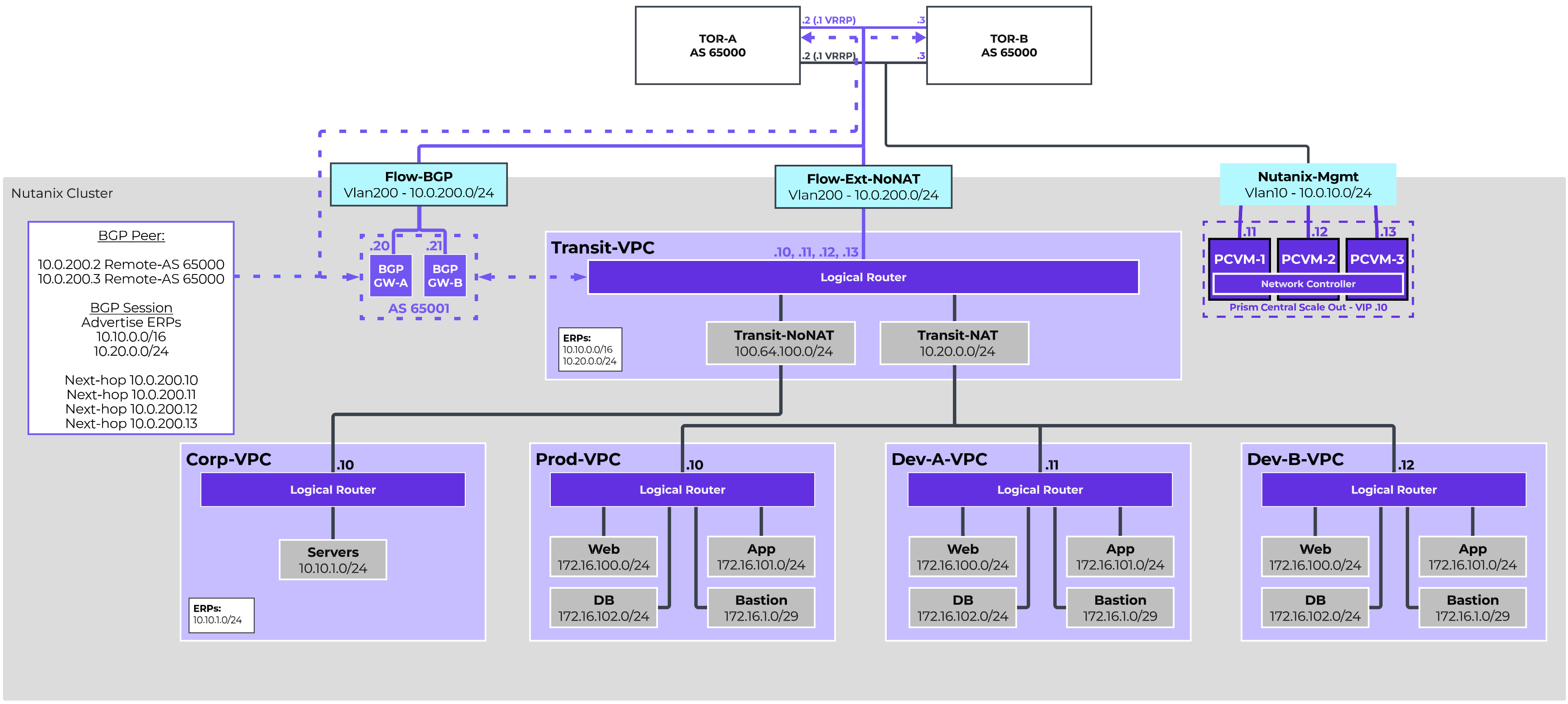
The Software as a Service Transit VPC Design is an example of how Flow Virtual Networking can simplify operations for a growing SaaS team looking for agility and security. This two-tier design utilizes a Transit VPC to provide centralized connectivity and services for multiple individually connected VPCs. Corporate resources are directly routable, while production and development environments are deployed using private repeated addressing.
The Corp-VPC will be directly routable, with the 10.10.0.0/16 address space allocated, so we will configure a NoNAT VLAN-backed External Network for our Transit VPC.
The Prod-VPC and individual Dev-VPCs will not be directly routable, and in fact will all have overlapping addressing. However, this can be accomplished within the Transit VPC, so we do not need to configure a NAT VLAN-Backed External Network.
Additionally, the network team requires that dynamic routing be utilized across the infrastructure, so BGP Gateways will be deployed to provide dynamic routing. We will configure two Subnets for VLAN200. One will be configured as the Routed External Network, and the other will allow the BGP Gateways to reside on the same network segment. To that end, the following VLAN-Backed Networks are configured:
| Name | Flow-Ext-NoNAT | Flow-BGP |
|---|---|---|
| VLAN ID: | 200 | 200 |
| Virtual Switch: | vs0 | vs0 |
| External Connectivity for VPCs: | Enabled | Disabled |
| NAT: | Disabled | N/A |
| IPAM: | Nutanix IPAM | External IPAM |
| Network CIDR: | 10.0.200.0/24 | 10.0.200.0/24 |
| Gateway: | 10.0.200.1 | 10.0.200.1 |
| IP Pool: | 10.0.200.10-10.0.200.19 | N/A |
The Transit VPC will be configured leveraging the Flow-Ext-NoNAT as the only external network. There is no need to set the external network as the static default route as we will learn routing via BGP. We will utilize 10.20.0.0/24 as a NAT pool for resources in connected VPCs, and thus we want to ensure that NAT range itself is considered externally routable, so we will define it as an Externally Routable IP Prefix along with the 10.10.0.0/16 that has been allocated for corporate resources.
| Name | Transit-VPC |
|---|---|
| Transit VPC: | Yes |
| External Subnet: | Flow-Ext-NoNAT |
| Set this subnet as default next hop for outbound traffic: | No |
| Destination Prefixes: | N/A |
| Router IP Assignment Mode: | Custom Defined |
| Custom Router IP: | 10.0.200.10, 10.0.200.11, 10.0.200.12, 10.0.200.13 |
| External Gateway Configuration: Number of Active Hosts | 4 |
| Externally Routable IP Prefixes: | 10.10.0.0/16, 10.20.0.0/24 |
For simplicity, we want to deploy the BGP gateways on the same VLAN as the VPC external network. As an External Network cannot be connected directly to a VM, we will create a non-external instance of VLAN200 called Flow-BGP. Configure this additional VLAN with External IPAM to avoid address conflicts. We will deploy two BGP gateways for high availability in Additional Paths mode to simplify configuration. The following Network Gateways will be configured:
| Gateway Name | BGP-GW-A | BGP-GW-B |
|---|---|---|
| Gateway Attachment: | VLAN | VLAN |
| Subnet: | Flow-BGP | Flow-BGP |
| DNS Configuration: | Inherit from Cluster | Inherit from Cluster |
| NTP Configuration: | Inherit from Cluster | Inherit from Cluster |
| Gateway Service: | BGP | BGP |
| Serviced VPC: | Transit-VPC | Transit-VPC |
| BGP Path Advertisement Configuration: | Advertise Multiple Routes | Advertise Multiple Routes |
| Static IP Address: | 10.0.200.20/24 | 10.0.200.21/24 |
| Default Gateway: | 10.0.200.1 | 10.0.200.1 |
| eBGP ASN: | 65001 | 65001 |
Each of the TOR switches will be configured as a remote gateway, and both BGP gateways will be peered to both TOR switches. This will enable the BGP gateways to advertise the configured Externally Routable IP Prefixes to both TORs with all four router IPs advertised as an eligible, installable path. The following Remote Gateways will be configured:
| Name | TOR-A | TOR-B |
|---|---|---|
| Gateway Service: | BGP | BGP |
| Service IP Address: | 10.0.200.2 | 10.0.200.3 |
| eBGP ASN: | 65001 | 65001 |
The following BGP Sessions will be configured:
| Local Gateway | BGP-GW-A | BGP-GW-A | BGP-GW-B | BGP-GW-B |
|---|---|---|---|---|
| Remote Gateway: | TOR-A | TOR-B | TOR-A | TOR-B |
| Session Name: | GW-A-TOR-A | GW-A-TOR-B | GW-B-TOR-A | GW-B-TOR-B |
| Advertised Externally Routable Prefixes: | All in VPC | All in VPC | All in VPC | All in VPC |
| Dynamic Route Priority: | Automatically Set | Automatically Set | Automatically Set | Automatically Set |
| Password: | None | None | None | None |
| AS Path Prepend: | None | None | None | None |
| Advertised Communities: | None | None | None | None |
Finally, we will want to configure the TORs to advertise a default route with the VRRP virtual IP as the next hop instead of their real IP. This is generally accomplished with a route map on most network infrastructure. With this added, new networks can be configured, and adding those addresses to the Transit-VPC’s Externally Routable IPs field will cause those addresses to be advertised to the physical infrastructure.
In this particular environment, there are no shared resources to deploy in the Transit. As such, we will only be configuring External Networks to provide connectivity to the connected VPC. Our NAT External Network will use the 10.20.0.0/24 address space, which will be advertised as routable and reachable by the Transit VPC’s BGP Gateways.
| Name | Transit-NAT | Transit-NoNAT |
|---|---|---|
| Subnet Type: | Overlay | Overlay |
| VPC: | Transit-VPC | Transit-VPC |
| External Connectivity for VPCs: | Yes | Yes |
| NAT: | Yes | No |
| IPAM: | Nutanix IPAM | Nutanix IPAM |
| Network CIDR: | 10.20.0.0/24 | 100.64.100.0/24 |
| Gateway: | 10.20.0.1 | 100.64.100.1 |
| IP Pool: | 10.20.0.10-254 | 100.64.100.10-254 |
VPCs will be created for Corporate resources, the Production environment, and individual Developer environments. This VPC is intended to be directly reachable, and will use the Transit-NoNAT External Network. The defined Externally Routable IP Prefixes will cause static routes to be created in the Transit VPC for each prefix with the connected VPC’s Router IP as the next hop.
The Production Environment and the Developer Environments will leverage identical IP addressing to ensure consistency across environments. However, they will each only have NAT Connectivity, helping to prevent accidental cross-communication. Floating IPs will be assigned to Network Load Balancer instances in each VPC that will be configured to balance HTTP and HTTPS traffic across the Web Servers.
Within the production and development environments, Bastion networks will be deployed to host jump servers. A Floating IP will be assigned to the Bastion host, allowing an entry point for management, monitoring, administration and development. There will be no direct inbound connectivity to the Web, App, or DB servers.
This design demonstrates a single production environment. However, additional VPCs can be created easily, with the number of VPCs dictated by the Prism Central sizing.
The following VPCs will be configured:
| Name | Corp-VPC | Prod-VPC | Dev-A-VPC | Dev-B-VPC |
|---|---|---|---|---|
| Transit VPC: | No | No | No | No |
| External Subnet: | Transit-NoNAT | Transit-NAT | Transit-NAT | Transit-NAT |
| Set this subnet as default next hop for outbound traffic: | Yes | Yes | Yes | Yes |
| Destination Prefixes: | 0.0.0.0/0 | 0.0.0.0/0 | 0.0.0.0/0 | 0.0.0.0/0 |
| Router IP Assignment Mode: | Custom Defined | Custom Defined | Custom Defined | Custom Defined |
| Custom Router IP: | 100.64.100.10 | 10.20.0.10 | 10.20.0.11 | 10.20.0.12 |
| Externally Routable IP Prefixes: | 10.10.0.0/16 | None | None | None |
The Corp-VPC holds corporate servers. Additional networks can be configured as needed for logical segmentation, but our initial design only requires a single server network.
| Name | Servers |
|---|---|
| Subnet Type: | Overlay |
| VPC: | Corp-VPC |
| IPAM: | Nutanix IPAM |
| Network CIDR: | 10.10.1.0/24 |
| Gateway: | 10.10.1.1 |
| IP Pool: | 10.10.1.100-199 |
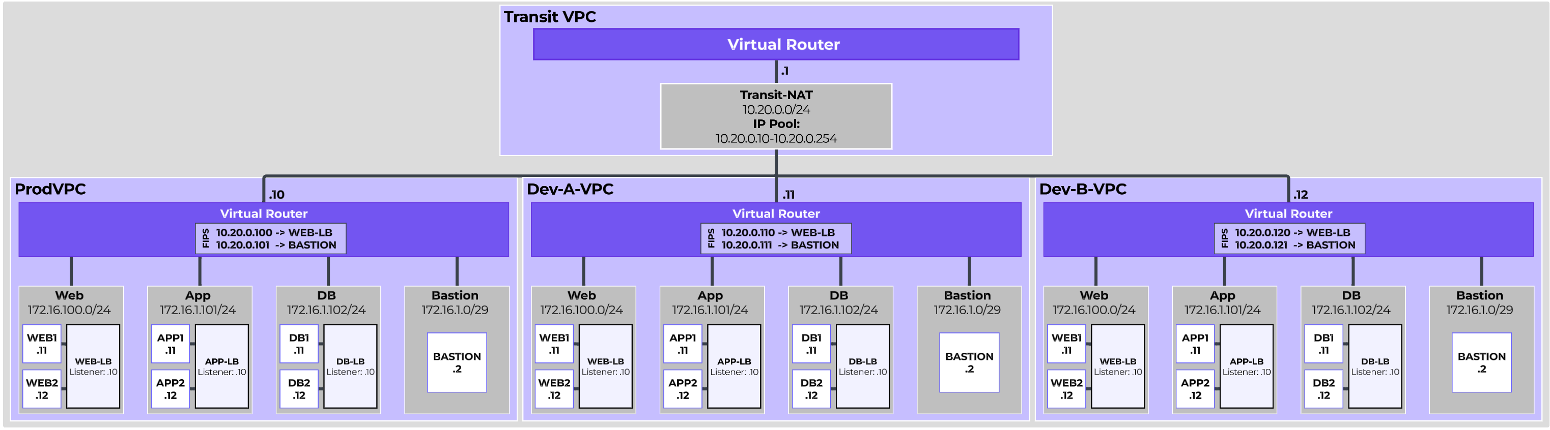
The Production and Development VPCs represent instances of the SaaS application, and will all have four identically configured subnets for ensuring consistency between dev and prod.The first three are for the Web, App, and DB servers for the application. The Bastion network is a small network for a jump server for administrative access, monitoring, and software deployment and distribution.
The subnets will be duplicated across multiple VPCs and look like this:
| Name | Web | App | DB | Bastion |
|---|---|---|---|---|
| Subnet Type: | Overlay | Overlay | Overlay | Overlay |
| VPC: | Multiple | Multiple | Multiple | Multiple |
| IPAM: | Nutanix IPAM | Nutanix IPAM | Nutanix IPAM | Nutanix IPAM |
| Network CIDR: | 172.16.100.0/24 | 172.16.101.0/24 | 172.16.102.0/24 | 172.16.1.0/29 |
| Gateway: | 172.16.100.1 | 172.16.101.1 | 172.16.102.1 | 172.16.1.1 |
| IP Pool: | 10.129.1.100-199 | 10.129.2.100-199 | 10.129.10.100-199 | 172.16.1.2-6 |
Each VPC will begin with two web servers, two app servers, two database servers, and a bastion host. Additionally, VPC Network Load Balancers will be deployed for all three tiers of the application. The Web Load Balancer will be assigned a Floating IP, allowing the Web Application to be accessible externally. The bastion host will also be assigned a Floating IP for external access. Naming for all resources will be prefixed to match the VPC. That is, Prod-VPC resources will be prefixed with ‘Prod-’.
The following Floating IPs will be allocated and assigned:
| External Subnet | Transit-NAT | Transit-NAT | Transit-NAT | Transit-NAT | Transit-NAT | Transit-NAT |
|---|---|---|---|---|---|---|
| Floating IP: | 10.20.0.100 | 10.20.0.101 | 10.20.0.110 | 10.20.0.111 | 10.20.0.120 | 10.20.0.121 |
| Assigned To: | Prod-Web-LB* | Prod-Bastion | Dev-A-Web-LB* | Dev-A-Bastion | Dev-B-Web-LB* | Dev-B-Bastion |
* Load balancer Floating IPs are pre-allocated and assigned during creation of the Load Balancer Session.
Network Load Balancers will be configured identically in each VPC. The Web NLBs will be assigned Floating IPs for external reachability. The App and DB NLBs are only accessible within the VPC and therefore will not be assigned Floating IPs. The Network Load Balancers will be configured as follows:
| Name | <Prefix>-Web-LB | <Prefix>-App-LB | <Prefix>-DB-LB |
|---|---|---|---|
| Listener | |||
| Protocol | TCP | TCP | TCP |
| Port | 443 | 8080 | 3306 |
| Subnet | <Prefix>-Web | <Prefix>-App | <Prefix>-DB |
| Primary Assignment Type | Provide Static IP | Provide Static IP | Provide Static IP |
| IP Address | 172.16.100.10 | 172.16.101.10 | 172.16.102.10 |
| Floating IP | See Above | None | None |
| Targets | |||
| VM NIC Selection Method | Select VM NICs Individually | Select VM NICs Individually | Select VM NICs Individually |
| Target VM NICs | <Prefix>-Web1/2 | <Prefix>-App1/2 | <Prefix>-DB1/2 |
| Health Check | |||
| Check Run Every | 5 Seconds | 5 Seconds | 5 Seconds |
| Time Out After | 2 Seconds | 2 Seconds | 2 Seconds |
| Marked Health After | 3 Consecutive Successes | 3 Consecutive Successes | 3 Consecutive Successes |
| Marked Unhealthy After | 3 Consecutive Failures | 3 Consecutive Failures | 3 Consecutive Failures |
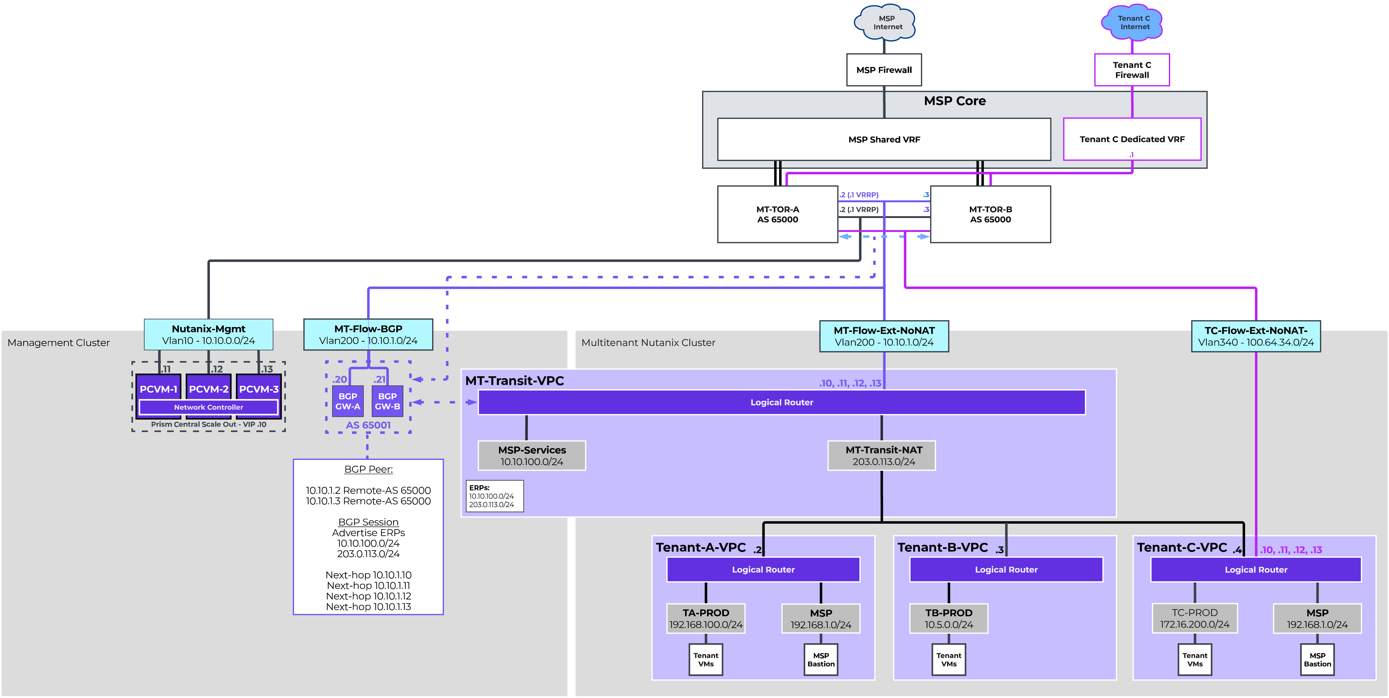
The Managed Service Provider Reference Architecture provides an example of how Flow Virtual Networking can provide isolated tenant networking within a shared provider environment, with the flexibility of both shared and dedicated connectivity deployment models.
This design includes two distinct clusters. A smaller management cluster hosts Prism Central and other provider management infrastructure. Client workloads are able to be distributed across one or more larger multitenant clusters.
A Transit VPC provides a centralized north/south NAT connectivity for tenants without their own dedicated connectivity. It also provides a connection point for access to optional MSP services, delivered via MSP bastion hosts. Tenants with their own dedicated connectivity can be provided dedicated External Networks. VRFs are an option to provide the network isolation for this dedicated connectivity on the physical network infrastructure.
All VLAN backed connectivity will be routed. An External Network will be configured on the multitenant cluster to provide connectivity to the shared Transit VPC. An additional Subnet will be configured with the same VLAN ID on the management cluster for BGP Gateways. While NAT does need to happen for the shared connectivity, that will be handled in the Transit VPC via Overlay. In the example, While Tenants A and B will be utilizing the shared connectivity, Tenant C will be utilizing dedicated connectivity. We will therefore need to configure an additional external network dedicated to Tenant C. Tenant C has opted to use the shared network space for its NoNAT external network.
| Name | MT-Flow-Ext-NoNAT | MT-Flow-BGP | TC-Flow-Ext-NoNAT |
|---|---|---|---|
| VLAN ID: | 200 | 200 | 340 |
| Virtual Switch: | vs0 - Multitenant Cluster | vs0 - Mgmt Cluster | vs0 - Multitenant Cluster |
| External Connectivity for VPCs: | Enabled | Disabled | Enabled |
| NAT: | Disabled | N/A | Disabled |
| IPAM: | Nutanix IPAM | External IPAM | Nutanix IPAM |
| Network CIDR: | 10.10.1.0/24 | N/A | 100.64.34.0/24 |
| Gateway: | 10.10.1.1 | N/A | 100.64.34.1 |
| IP Pool: | 10.10.1.10-100 | N/A | 100.64.34.10-19 |
The Shared Transit VPC provides centralized north/south NAT connectivity as well as hosts shared resources for managing and monitoring the environment. It will be configured leveraging the Flow-Ext-NoNAT-MT as the only external network. There is no need to set the external network as the static default route as we will learn routing via BGP.
The MSP has allocated a block of Public IPs, 203.0.113.0/24, to be provided to clients as external SNAT IPs and Floating IPs. Thus we want to ensure that NAT range itself is considered externally routable, so we will define it as an Externally Routable IP Prefix along with the 10.10.100.0/24 that has been allocated for MSP Management resources.
| Name | MT-Transit-VPC |
|---|---|
| Transit VPC: | Yes |
| External Subnet: | MT-Flow-Ext-NoNAT |
| Set this subnet as default next hop for outbound traffic: | No |
| Destination Prefixes: | N/A |
| Router IP Assignment Mode: | Custom Defined |
| Custom Router IP: | 10.10.1.10, 10.10.1.11, 10.10.1.12, 10.10.1.13 |
| External Gateway Configuration: Number of Active Hosts | 4 |
| Externally Routable IP Prefixes: | 10.10.100.0/24, 203.0.113.0/24 |
Like the other VPC design examples, we want to deploy the BGP gateways on the same VLAN as the VPC external network. As we want to house the BGP gateways on the Management Cluster, the Flow-BGP-MT subnet was built on the management cluster’s vs0. Configure this additional VLAN with External IPAM to avoid address conflicts. We will deploy two BGP gateways for high availability in Additional Paths mode to simplify configuration. The following Network Gateways will be configured:
| Gateway Name | BGP-GW-A | BGP-GW-B |
|---|---|---|
| Gateway Attachment: | VLAN | VLAN |
| Cluster: | Management | Management |
| Subnet: | MT-Flow-BGP | MT-Flow-BGP |
| DNS Configuration: | Inherit from Cluster | Inherit from Cluster |
| NTP Configuration: | Inherit from Cluster | Inherit from Cluster |
| Gateway Service: | BGP | BGP |
| Serviced VPC: | MT-Transit-VPC | MT-Transit-VPC |
| BGP Path Advertisement Configuration: | Advertise Multiple Routes | Advertise Multiple Routes |
| Static IP Address: | 10.10.1.20/24 | 10.10.1.21/24 |
| Default Gateway: | 10.10.1.1 | 10.10.1.1 |
| eBGP ASN: | 65001 | 65001 |
Each of the TOR switches will be configured as a remote gateway, and both BGP gateways will be peered to both TOR switches. This will enable the BGP gateways to advertise the configured Externally Routable IP Prefixes to both TORs with all four router IPs advertised as an eligible, installable path. The following Remote Gateways will be configured:
| Name | TOR-A | TOR-B |
|---|---|---|
| Gateway Service: | BGP | BGP |
| Service IP Address: | 10.10.1.2 | 10.10.1.3 |
| eBGP ASN: | 65000 | 65000 |
The following BGP Sessions will be configured:
| Local Gateway | BGP-GW-A | BGP-GW-B | ||
|---|---|---|---|---|
| Remote Gateway: | TOR-A | TOR-B | TOR-A | TOR-B |
| Session Name: | GW-A-TOR-A | GW-A-TOR-B | GW-B-TOR-A | GW-B-TOR-B |
| Advertised Externally Routable Prefixes: | All in VPC | All in VPC | All in VPC | All in VPC |
| Dynamic Route Priority: | Automatically Set | Automatically Set | Automatically Set | Automatically Set |
| Password: | None | None | None | None |
| AS Path Prepend: | None | None | None | None |
| Advertised Communities: | None | None | None | None |
Finally, we will want to configure the TORs to advertise a default route with the VRRP virtual IP as the next hop instead of their real IP. This is generally accomplished with a route map on most network infrastructure. With this added, new networks can be configured, and adding those addresses to the MT-Transit-VPC’s Externally Routable IPs field will cause those addresses to be advertised to the physical infrastructure.
The MSP has management and monitoring resources deployed in the Transit, so an MSP-Management network will be configured. Flow Network Security policies can be configured to secure access to/from these resources as needed.
A NAT Overlay External Network will be configured. The public IP block 203.0.113.0/24 has been assigned for this purpose. This NAT Overlay Network will primarily be used to provide access to shared ISP connectivity, but it also serves as an entry point for MSP Management access. Floating IPs can be assigned to tenant workloads for external access as needed. Floating IPs will also be assigned to MSP management Bastion hosts to provide access.
| Name | MSP-Management | MT-Transit-NAT |
|---|---|---|
| Subnet Type: | Overlay | Overlay |
| VPC: | MT-Transit-VPC | MT-Transit-VPC |
| External Connectivity for VPCs: | No | Yes |
| NAT: | N/A | Yes |
| IPAM: | Nutanix IPAM | Nutanix IPAM |
| Network CIDR: | 10.10.100.0/24 | 203.0.113.0/24 |
| Gateway: | 10.10.100.1 | 203.0.113.1 |
| IP Pool: | 10.10.100.100-199 | 203.0.113.2-254 |
Tenant VPCs will provide isolated network spaces for each tenant. Tenants have the option to leverage shared MSP connectivity or dedicated connectivity.
Tenants that purchase MSP services that require the MSP be able to monitor and manage Tenant VMs directly will have a MSP Bastion VM put on an MSP network in their VPC, and a Floating IP will be assigned to the Bastion VM.
Tenant VPCs that leverage dedicated connectivity can also connect to the Transit VPC for access to MSP management resources, and Tenant C is configured in this manner. VPC Network Policies are configured to policy route the Bastion VM through the NAT External Network. Tenant C has procured their own ISP connection and firewalls. A VRF is provisioned on the MSP network infrastructure to support this dedicated, isolated connectivity. Tenant C will not be leveraging dynamic routing. Static routes will be provisioned in their dedicated VRF as needed, and their VPC will be configured with a static default route.
In our design, the following VPCs will be configured.
| Name | Tenant-A-VPC | Tenant-B-VPC | Tenant-C | Tenant-C |
|---|---|---|---|---|
| Transit VPC: | No | No | No | No |
| External Subnet: | MT-Transit-NAT | MT-Transit-NAT | MT-Transit-NAT | TC-Flow-Ext-NoNAT |
| Set this subnet as default next hop for outbound traffic: | Yes | Yes | No | Yes |
| Destination Prefixes: | 0.0.0.0/0 | 0.0.0.0/0 | 0.0.0.0/0 | |
| Router IP Assignment Mode: | Auto-Assigned | Auto-Assigned | Auto-Assigned | Custom Defined |
| Custom Router IP: | N/A | N/A | N/A | 100.64.34.10,11,12,13 |
| Externally Routable IP Prefixes: | None | None | None | 172.16.200.0/24 |
Tenant A leverages shared connectivity via MT-Transit-VPC and also subscribes to management services. The following overlay subnets will be configured for Tenant A.
| Name | TA-Prod | MSP |
|---|---|---|
| Subnet Type: | Overlay | Overlay |
| VPC: | Tenant-A-VPC | Tenant-A-VPC |
| IPAM: | Nutanix IPAM | Nutanix IPAM |
| Network CIDR: | 192.168.100.0/24 | 192.168.1.0/24 |
| Gateway: | 192.168.100.1 | 192.168.1.1 |
| IP Pool: | 192.168.100.100-199 | 192.168.1.100-199 |
An MSP Bastion VM will be deployed in the MSP network, and a Floating IP will be allocated from MT-Transit-NAT’s IP Pool. VPC Network Policies and/or Flow Network Security can be used to limit the traffic allowed to/from the MSP Bastion VM.
Tenant B leverages shared connectivity via MT-Transit-VPC, but does not subscribe to any management services. The following overlay subnet will be configured for Tenant B.
| Name | TB-PROD |
|---|---|
| Subnet Type: | Overlay |
| VPC: | Tenant-B-VPC |
| IPAM: | Nutanix IPAM |
| Network CIDR: | 10.5.0.0/24 |
| Gateway: | 10.5.0.1 |
| IP Pool: | 10.5.0.2-254 |
Tenant C has purchased dedicated connectivity, and also subscribes to MSP Management services. The following overlay subnets will be configured for Tenant C.
| Name | TC-PROD | MSP |
|---|---|---|
| Subnet Type: | Overlay | Overlay |
| VPC: | Tenant-C-VPC | Tenant-C-VPC |
| IPAM: | Nutanix IPAM | Nutanix IPAM |
| Network CIDR: | 172.16.200.0/24 | 192.168.1.0/24 |
| Gateway: | 172.16.200.1 | 192.168.1.1 |
| IP Pool: | 172.16.200.5-100 | 192.168.1.2-254 |
An MSP Bastion VM will be deployed in the MSP network, and a Floating IP will be allocated from MT-Transit-NAT’s IP Pool. VPC Network Policies and/or Flow Network Security can be used to limit the traffic allowed to/from the MSP Bastion VM.
Additionally, a VPC Network Policy will be configured to ensure all traffic sourced from the MSP network and bound for an external destination is forwarded to the MT-Transit-NAT external network’s default gateway. This Network Policy is configured as shown:
| Policy Priority | 900 |
|---|---|
| Source | Custom |
| Source Subnet IP | 192.168.1.0/24 |
| Destination | External |
| Protocol | Any |
| Action | Forward |
| Forward IP | 203.0.113.1 |
©2025 Nutanix, Inc. All rights reserved. Nutanix, the Nutanix logo and all Nutanix product and service names mentioned are registered trademarks or trademarks of Nutanix, Inc. in the United States and other countries. All other brand names mentioned are for identification purposes only and may be the trademarks of their respective holder(s).