» Download this section as PDF (opens in a new tab/window)
Delivering security at cloud velocity.
Traditional network security has long relied on a castle and moat philosophy, where perimeter firewalls guard the north-south boundary while leaving the internal network largely flat and unprotected.
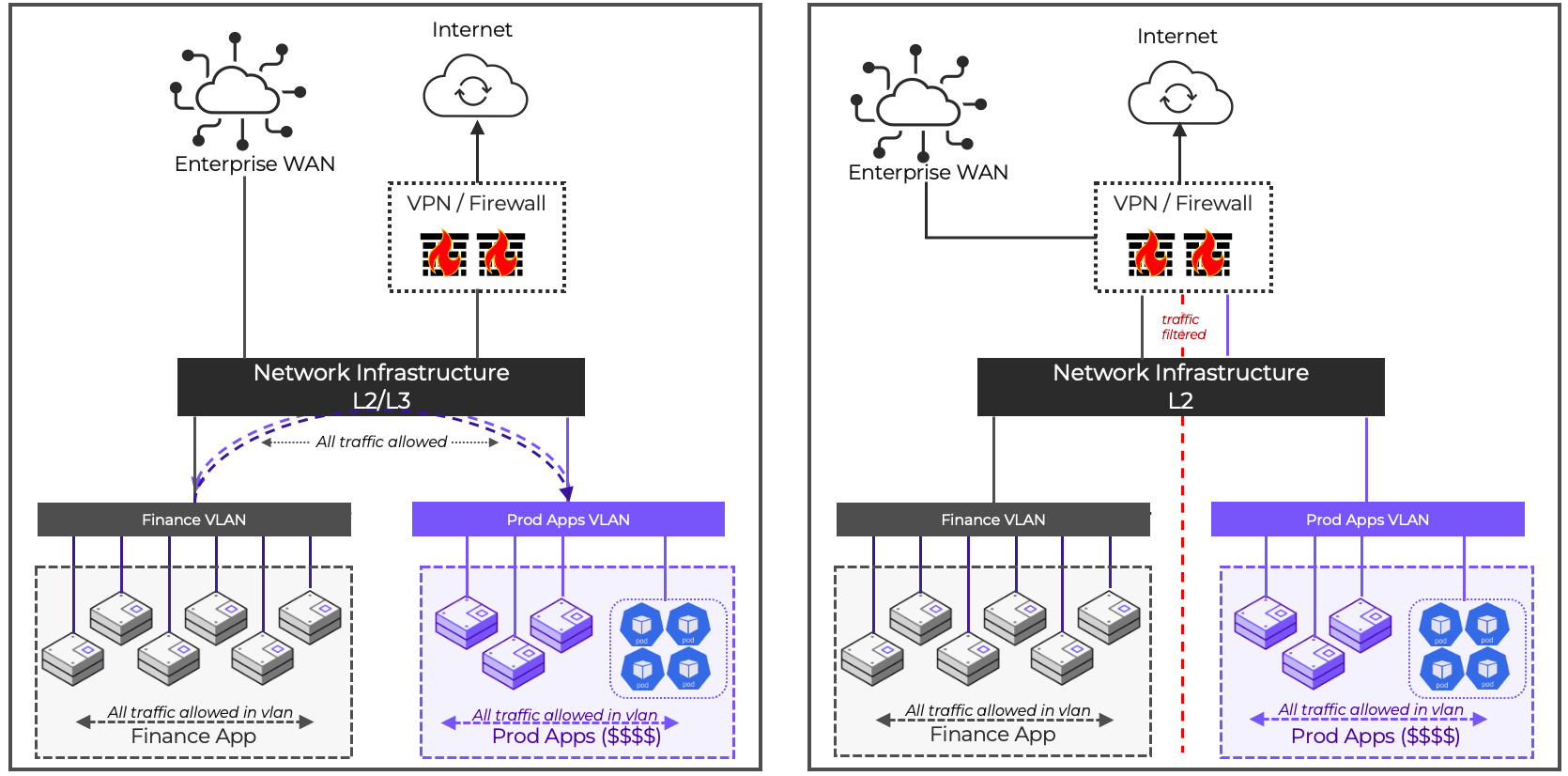
In modern, highly virtualized data centers, this reliance on perimeter based security creates a massive blind spot: lateral movement. Once an attacker breaches the edge, they can move freely between workloads (east-west traffic) because traditional perimeter architectures are physically and logically incapable of inspecting traffic at the granular vNIC level. The alternative is to force all internal traffic through a centralized hardware appliance or virtual gateway. This process can introduce latency, performance bottlenecks, and administrative challenges. Additionally, these static, IP-based systems struggle to keep pace with the ephemeral nature of virtual machines and containers. Without a distributed security model, the blast radius of a single compromised asset remains unchecked, as the perimeter firewall remains unaware of the malicious activity happening right behind it.
Microsegmentation solves this challenge by policing traffic within network segments, implementing per-host security policies to fully govern east-west traffic.
Nutanix Flow Network Security (FNS) redefines workload protection by embedding an agentless, stateful, distributed firewall directly into the hypervisor layer. By shifting security enforcement from traditional network perimeters straight to individual virtual machines and containers, Flow decouples security from physical network topologies.
Using flexible, intent-based categories, it drives a Zero Trust architecture across hybrid cloud environments. The core business value is simple: FNS neutralizes lateral threat movement (east-west traffic) and drastically shrinks the blast radius of security incidents, all without the operational headache of manual firewall configuration or guest agent maintenance.
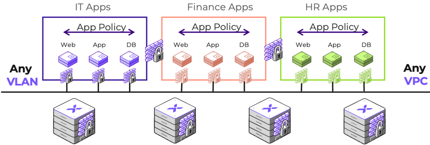
Flow Network Security is built around the Application-Centric Policy Model. Instead of a single monolithic list of firewall rules for the entire environment, the Application-Centric Model defines security in the context of a particular Application, applied via a policy.
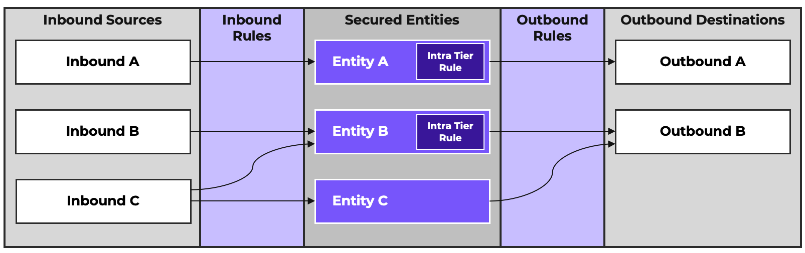
Policies define an application as a collection of Secured Entities. These are the components of the application you wish to secure. In a traditional three-tier application, this could be Web, App, and Database. Other applications may have different components. Some applications may have just one while other applications could have more. Secured Entities are typically categories or entity groups defining specific VMs, but they can also be network constructs like VPCs, subnets, or groups of IP addresses.
An FNS policy has Inbound Sources and Outbound Destinations. These are the resources that our secured entities will receive traffic from or send traffic to. In cases where one secured entity needs to communicate with another, your secured entity may also be reflected as a source or destination. Sources and destinations can be categories, entity groups, and network constructs. They can also be “Allow All” for rules that allow traffic from any source or to any destination.
Intra-Tier Rules define traffic allowed between the members of a Secured Entity. Intra-Tier rules can be applied in three ways:
The Intra-Tier Rule section is not required or may need more granular definition beyond allow all or deny all. For this reason, the Intra-Tier Rule can also be removed for a Secured Entity. It is recommended that the Intra-Tier rule be removed for any entity that doesn’t require intra-tier traffic to explicitly be policed. This is especially important for broad secured entities used to define rules environment-wide.
Inbound Rules define traffic a Secured Entity is allowed to receive from an Inbound Source. Outbound Rules define the traffic a Secured Entity is allowed to send to an Outbound Destination. These rules define the allowed TCP, UDP and ICMP traffic. Any traffic not defined as allowed is implicitly denied by default. All Secured Entities, when initially added to a policy, have an Allow All Outbound rule created by default.
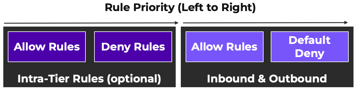
Intra-Tier rules are processed before Inbound and Outbound rules. Traffic denied by an Intra-Tier rule cannot be allowed by an Inbound or Outbound rule, as the Intra-Tier deny will happen first.
Policies can be configured for IPv4 and/or IPv6. When configuring a policy for IPv4 mode only, you have the option to either allow all IPv6 traffic or block all IPv6 traffic. As many modern operating systems will automatically configure IPv6, it is recommended to block all IPv6 traffic to prevent a malicious actor from taking advantage of unsecured IPv6 communication. IPv6 policies are only available for VLAN-scoped policies.
The following are the building blocks of Nutanix Flow Network Security.
In Nutanix, categories serve as the foundational building blocks for microsegmentation and policy enforcement. Structured as Key:Value pairs, they describe a virtual machine’s (VM) or container’s specific purpose, environment, or functional context.
Here is how the hierarchy breaks down:
AppType or EnvironmentExchange or Production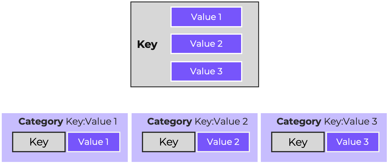
Every distinct Key:Value combination forms a unique category, allowing Flow Network Security to dynamically group VMs and apply precise security policies based on logical attributes rather than network addresses.
Take a common key like Environment. Under this key, you might have values like Production, Staging, Dev, and QA. When you pair them up—such as Environment:Production or Environment:Dev—you get unique, individual categories ready for policy enforcement.
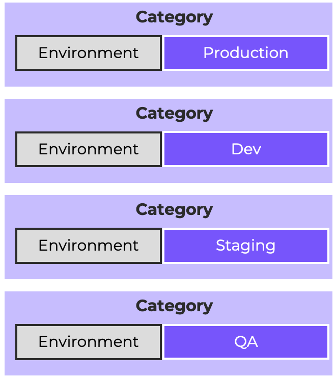
Note: The absence of a category should not be used as the positive affirmation of VM functionality or context. For instance, if you need to clearly identify that a VM is either Prod or NonProd , create Environment:Prod and Environment:NonProd as distinct categories. Do not rely on the absence of Environment:Prod to imply that a VM belongs to NonProd , because you can never be sure whether the absence of Environment:Prod is intentional or not.
Nutanix gives you plenty of flexibility with how you manage these, split into two main types:
VMs are not limited to just one category, assigning multiple categories is often a good practice. Here’s a quick example of how that looks in action:
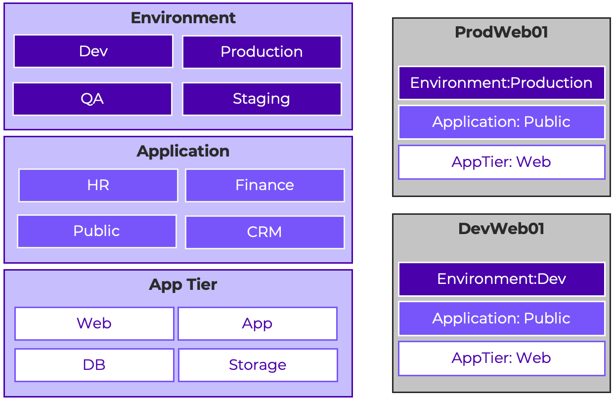
VM ProdWeb01 and VM DevWeb01 are both web servers for an application called Public. They are both assigned the AppTier:Web and Application:Public categories. However, they belong to different environments, with VM ProdWeb01 belonging to Environment:Production and VM DevWeb01 belonging to Environment:Dev.
As you are thinking about categories, remember they are best applied as broad labels. Avoid creating many hyper-specific categories, as that becomes difficult to manage, especially as environments grow in size and complexity. That said, there may be times where a single VM might need to be secured. The two possible approaches to consider are:
It is possible to automatically assign VMs to categories by way of NCM Playbooks. This is beyond the scope of this material, but the Nutanix developer resource site, Nutanix.dev, has a sample playbook that demonstrates auto-categorization by VM OS if you are interested in learning more.
Service Groups define reusable definitions of the ports and protocols used for a particular application or purpose. In addition to user-defined service groups, there are many built in services for common applications. Service groups can include TCP ports, UDP ports, and/or specific ICMP types and codes. However, they are not nestable.
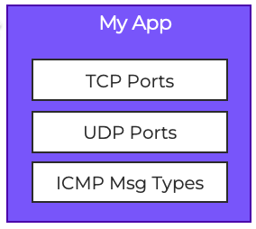
Note: Some built-in service groups use non-traditional port definitions. For instance, the built-in definition for http specifies both TCP/80 and UDP/80. Custom services should be created and used as needed to avoid any issues that might arise from the non-traditional ports.
Address Groups are custom definitions of IP addresses, ranges, and networks for use in entity groups and security policies. Address groups have a limit of 250 entries and are not nestable.
Check the Nutanix portal for updates to the configuration maximums
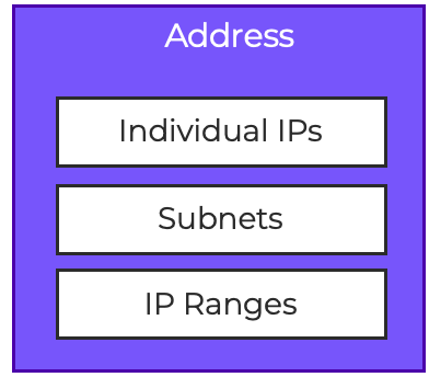
When defining entries for individual hosts in an address group, it is suggested to use CIDR notation with /32. Adding a host address without a network prefix results in a single-address range being created.
Entity Groups act as flexible logical containers that bundle different infrastructure components like VMs, subnets, VPC, and Kubernetes pods as a group. These groups allow you to map security policies directly to business intent by serving as inbound sources, outbound destinations, or secured entities. The power of an Entity Group lies in its intersection logic: when applied to an application or isolation policy, FNS evaluates the overlap of the attached categories to dynamically protect only the specific workloads that match all criteria. This approach simplifies microsegmentation by letting you deploy granular yet adaptable, zero-trust guardrails that automatically scale alongside your environment.
Entity Groups can be used to:
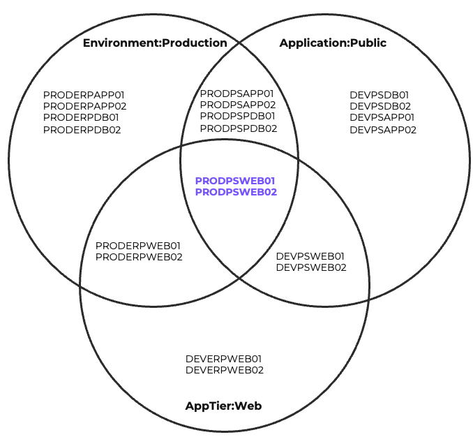
The most common of these is defining VMs that share categories. Consider the diagram below. Of the 20 VMs in the diagram, only PRODPSWEB01 and PRODPSWEB02 share the Environment:Production, Application:Public, and AppTier:Web categories. An Entity Group can be created targeting these three categories to define the VMs that live at that intersection. This Entity Group’s membership will be dynamically updated as needed based on category application changes.
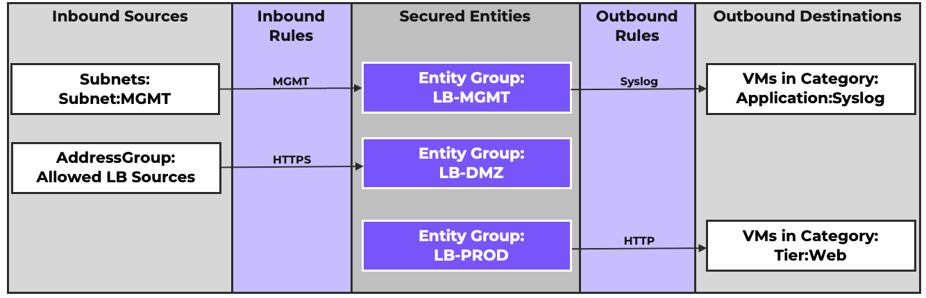
When a VM becomes a secured entity, any rules created apply to all vNICs of that VM. Combining VM categories and Subnet categories can allow an entity group to target specific vNICs. A common use case would be a load balancer with multiple NICs hosting VIPs for different services. When VMs have multiple vNICs on different subnets, targeting them via an Entity Group lets you create rules at the individual interface level ensuring that only the required traffic reaches the right vNIC, rather than applying a blanket rule to the VM as a whole.
IP-based Entity Groups can be created either by targeting an address group or by specifying a network address directly. When an IP-based Entity Group is used in a policy, any vNICs identified with the specified IP addresses will be included in the Secured Entity. VMs and vNICs are identified for inclusion in entity groups based on the IP addresses assigned by Nutanix IPAM or discovered by AHV observing DHCP/ARP traffic. For an example of how this works, see the NIC-Specific Policies for Multi-Homed VMs policy design example below.
IP-based Entity Groups also allow for exclusions. An address or address group can be defined as the base of the Entity Group, and a second address or address group can be defined for exclusion from the base. Consider the following example:
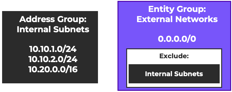
An address group called Internal Subnets is defined to include three CIDR ranges used within an organization. An Entity Group called External Networks is defined with the base of 0.0.0.0/0 (all IPs), excluding the Internal Subnets address group. The result will be an Entity Group that defines every non-Internal Subnet IP address. This Entity Group will dynamically adjust if the Internal Subnets address group is modified. For examples of how this can be used to simplify policies, see the Outbound Rules for North/South Traffic policy design example below.
Nutanix Flow Network Security provides targeted policy types to govern microsegmentation rules across virtual machines, VPCs, containers and user identities. Along with these policy types, there are different operating modes or policy states that a security policy may be placed in.
Quarantine Policies allow you to quickly and easily isolate workloads suspected of malware and compromise. There are two types of Quarantine Policy, both of which follow the Application-Centric Policy Model.
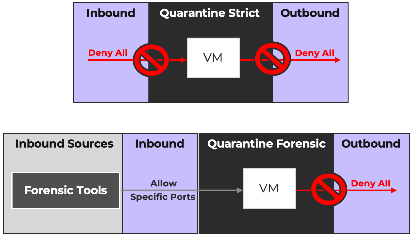
A VLAN-Scoped Quarantine Strict and Quarantine Forensic policy exists by default. Additional Strict and Forensic policies will be created automatically for each Flow Virtual Networking Virtual Private Cloud.
VMs can be quarantined or unquarantined via the Prism Central UI or via API calls. For example, an XDR platform that detects malicious behavior from a VM could automatically quarantine the VM by sending the Prism Central API calls to apply the appropriate Quarantine category to the VM.
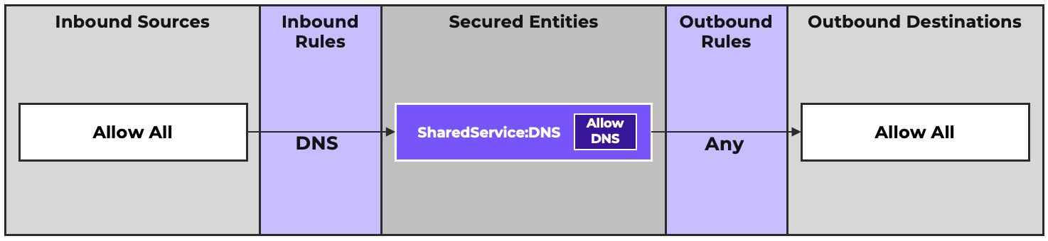
Shared Service Policies are special Application-Centric policies intended to define the inbound and outbound traffic for infrastructure services. Shared Service Policies are limited to a single Secured Entity, which must be a VM-based category from the SharedService key. There are built in SharedService categories for Active Directory, SMTP, NTP, DNS, and DHCP. Additional categories can be user-defined as needed. Inbounds and Outbounds can be freely defined as needed. Shared Service Secured Entities can then be added as Inbound Sources or Outbound Destinations within Application policies as needed.
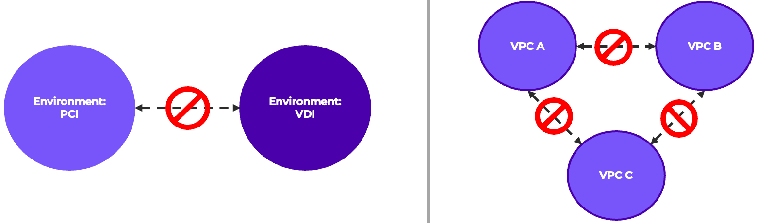
Isolation Policies allow you to explicitly block all traffic between two or more entities. Unlike the other policy types, they do not have definable inbound and outbound rules, and instead explicitly drop traffic between the isolated entities. Some common examples include:
Application Policies are the primary policy type within Flow Network Security. The Secured Entities in an Application Policy can be VMs, Subnets, VPCs, or Entity Groups. An example Application policy for a two-tier application is shown:
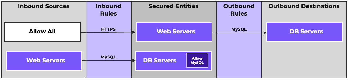
The Secured Entities are the DB Servers and the Web Servers. Allow All, is an inbound source and an Inbound Rule allowing HTTPS traffic to the Web Servers. The DB servers are also an Outbound Destination with an Outbound Rule allowing the Web Servers to send MySQL traffic to the DB servers. To complete this requirement, the Web Servers are also an Inbound Source with an Inbound Rule allowing the DB servers to receive the MySQL traffic from the Web Servers.
The DB Servers have an Intra-Tier Rule allowing them to communicate with each other via the MySQL port for replication. The Web Servers have no need to communicate with each other, so we do not configure any intra-tier rule. A Deny All Intra-Tier rule could be added if this traffic needed to be explicitly prevented.
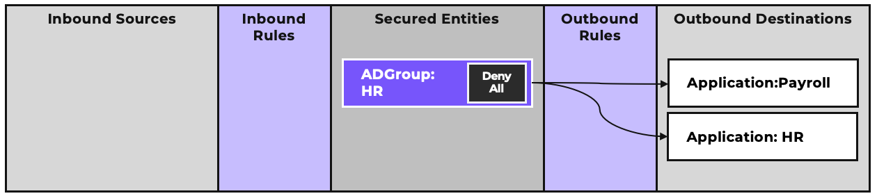
VDI Policies are a subset of Application Policies intended to provide Active Directory Group-based security to VDI workloads. Active Directory groups are defined and assigned to a category. VDI VMs and their associated IPs are identified according to defined filters. Prism Central monitors logon events on specified Active Directory servers. A VDI policy uses the AD Group-based categories as secured entities. When a Logon event happens for a member of a defined group on a VDI VM the VDI policy will identify that VM as a member of the Secured Entity. VDI policies only support VDI desktops with a single logged-on user, and should not be used with shared terminal servers. In the example below, a VDI policy for members of the HR group grants access to the Payroll and HR applications.
Policy Scope defines the VMs which a policy can potentially secure. Only VMs within a policy’s scope will be included as Secured Entities.
When a VLAN-scoped policy uses a category as a Secured Entity, and that category also includes VMs on VPC networks, the VPC based VMs will not be considered a part of the secured entity.
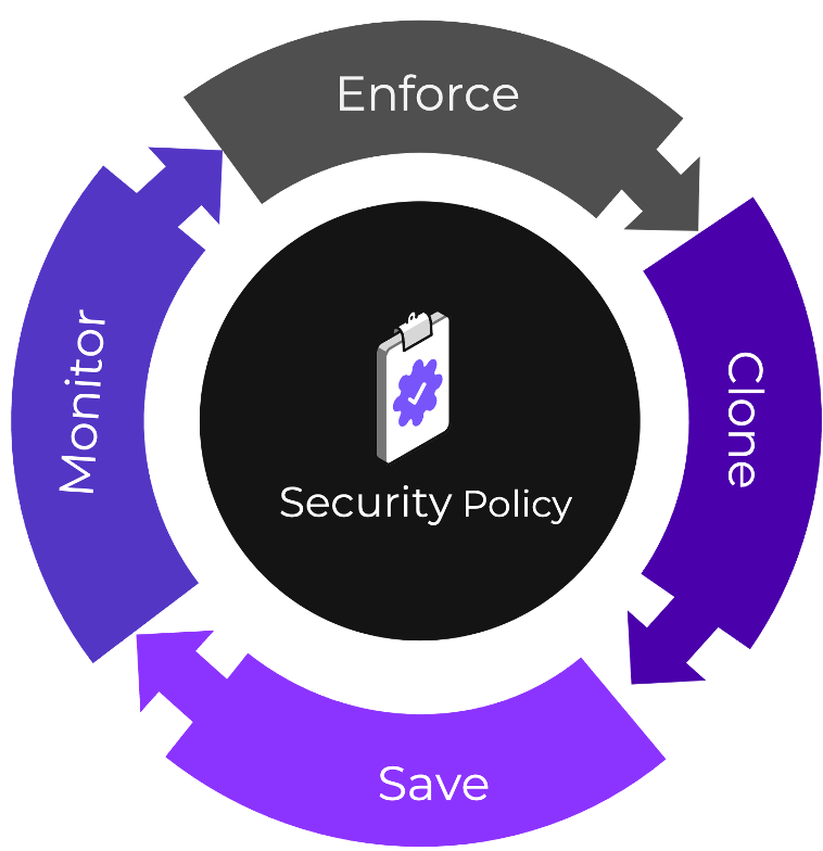
Saved Mode allows a policy to be defined but not active. This can be used while a policy is being built or refined without affecting traffic. Saved policies are also useful as templates that new policies can be cloned from.
Enforced Mode activates the policy completely, allowing only the defined traffic. When a policy results in blocked traffic, that traffic can be displayed as Discovered traffic. This can be useful for troubleshooting. If a policy is applied, and an application stops working as expected, you can look at the discovered traffic and identify if a traffic flow was missed. You can then modify the policy to add the desired discovered traffic. Viewing the discovered traffic is also a valuable security tool to identify unexpected traffic flows that require further investigation at the VM level. Discovered traffic remains visible for 24 hours.
Monitoring Mode is used to observe VMs and identify traffic to or from those VMs. It can be used for gathering information about VMs, or as a way of identifying any unforeseen consequences of a proposed rule before it is enforced. A policy in monitor mode explicitly allows all traffic while identifying what traffic would be blocked according to the policy should the policy be set to enforce mode. Monitor Mode policies are the lowest priority, and only are active for a VM if there are no other enforced policies of any type.
The policy evaluation order is determined by policy mode and policy type. Each Application-Centric Policy Type, when applied, has a default drop rule for any traffic not otherwise allowed. During evaluation, once a packet hits either an Allow, Drop, or Monitor action from a rule, no further processing takes place. Enforced policies are prioritized first in the order of Quarantine Strict, Quarantine Forensic, Shared Services, Isolation, and Application. Monitoring policies of any type are only considered if a VM is not subject to an Enforced policy. Finally, a VM that isn’t subject to any policies will not be policed by Flow Network Security at all and will be allowed to send and receive all traffic.
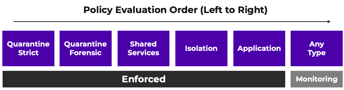
Consider the following scenarios where a VM is included as a secured entity in multiple policies.
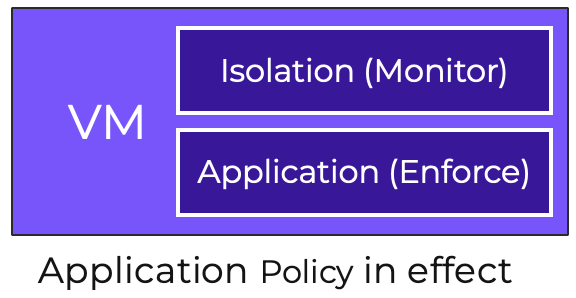
In the first scenario, a VM has an Isolation Policy in Monitor Mode and an Application Policy in Enforce Mode. In this case, only the Application policy will be in effect. Any traffic not allowed by the Application policy will be dropped, and therefore will never be considered by the Isolation Policy’s monitoring rules.
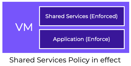
In the second scenario, a VM has a Shared Service Policy in Enforced Mode and an Application Policy in Enforced Mode. In this case, only the Shared Service policy will be in effect. Any traffic not allowed by the Shared Service policy will be dropped, and therefore will therefore never be considered by the Application Policy’s enforced rules.
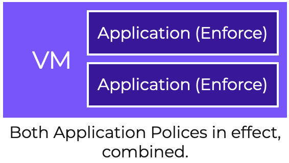
In the third scenario, a VM has two Application Policies in Enforced Mode. In this case, both policies will be in effect. Policy rules of the same type are additive. A VM’s effective rule set will include the combined inbound ruleset for each rule section.
Consider the example below:
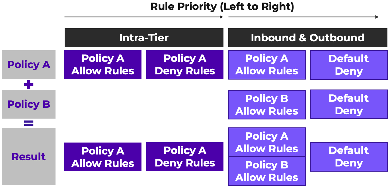
In this use case, a VM is in two Application Policies.
In Policy A, the VM is a member of a Secured Entity with an Intra-Tier rule as well as Inbound and Outbound rules. In Policy B, the VM is a member of a Secured Entity without an Intra-Tier rule, but does have defined Inbound and Outbound rules. The effective rule-set will have the Intra-Tier rule from Policy A considered first, and then the Inbound/Outbound allow rules from Policy A and Policy B considered next, with any traffic not defined in the allow rules, denied. This means that if Policy A’s Intra-Tier rule causes traffic to be denied, that deny cannot be overridden by an Allow rule in Policy B.
There are two types of logs relevant to Flow Network Security. API Audit logs provide a record of policy creation, modification, and deletion. Policy hit logs provide a record of traffic policed or monitored by an FNS policy. Policy hit logs are enabled on a per-policy basis. The logging mechanism for Flow Network Security is Syslog, configured via Prism Central. Policy hit log Syslog messages originate from the individual AHV hosts, as that is where policy enforcement occurs. API Audit logs originate from the Prism Central, since that’s the management plane where policies are edited.
Policy hit logs have three action types within the syslog message: Allow, Drop, and Monitor. Allow and Drop rules indicate actual enforcement actions. The Monitor action indicates that the traffic was observed by a Monitoring policy and allowed.
Policy hit logs have three event types: New, Update, and Destroy.
New events happen on the first packet of a session, whether it is allowed or denied.
Update events occur periodically for all active sessions for allowed traffic, updating the traffic statistics for the session.
Destroy events happen on session closed.
If you want to identify how many times a particular policy or rule was hit, count the number of New events for the rule. If you want to identify the amount of traffic for a particular policy or rule, add the traffic statistics from all the Destroy events. In either case, Update events should not be considered, and are merely informational progress indications of ongoing sessions.
For instructions on building a syslog server to capture logs from Flow Network Security, see How to Monitor Flow Network Security Using Graylog posted on Nutanix.Dev.
Flow Network Security policies can be backed up and restored via the Prism Central GUI. These backups are snapshots of the current configuration. Restoring a backup will revert Flow Network Security policies and policy objects to the state when the backup was taken. Any policies created after the backup will be deleted. Any policy changes made after the backup will be reverted. If you wish to back up the state of a single policy before making changes, there are two options:
The Entity Sync feature of Prism Central allows Security Policies and their related objects (categories, address groups, service groups, and entity groups) to be synchronized to Prism Central in another availability zone. This ensures that a VM can maintain its security posture during a Disaster Recovery event. Entity Sync is bidirectional. Changes made to a policy or object on either side of the Entity Sync pairing will be synchronized to the other side.
Flow Network Security extends microsegmentation to the Nutanix Kubernetes Platform (NKP) , providing a single management plane in Prism Central for both VMs and Pods. Policies use industry standards Cilium CNI Network Policies and support up to 25 K8s clusters from one console. This provides security admins one unified interface, one policy language, and one audit trail, eliminating fragmentation and enabling true Zero Trust across heterogeneous infrastructure.
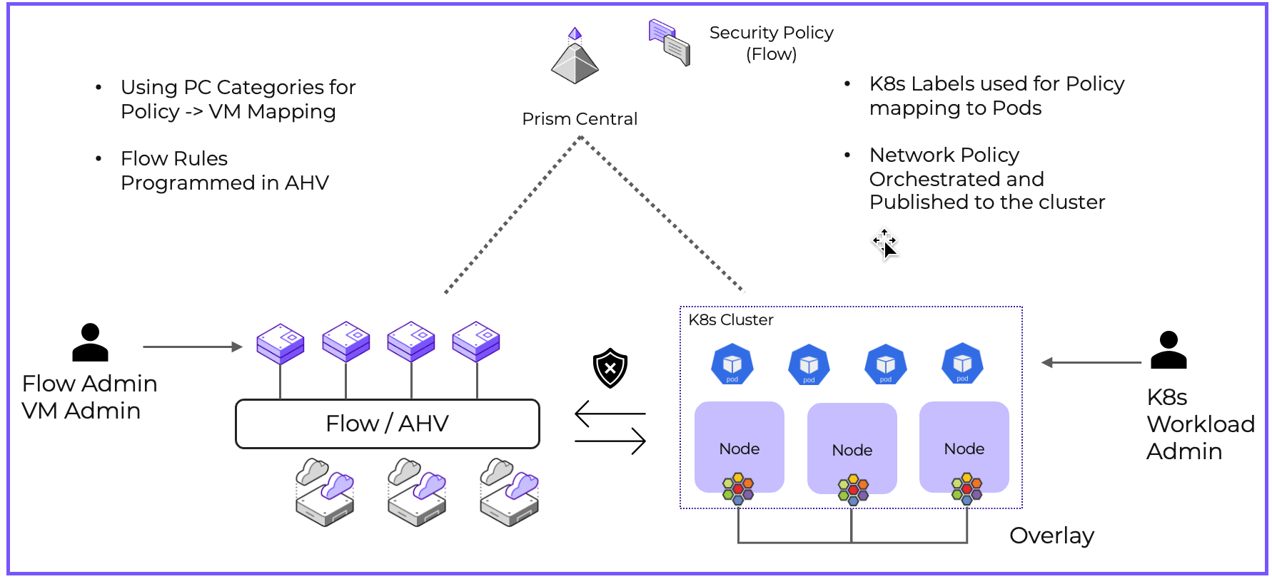
Security admins define policies in Prism Central using Entity Groups (collections of Pods by labels, Services by name, or Namespaces). Workload admins apply K8s labels to their Pods. Prism Central orchestrates policies to the cluster, where a lightweight Network Controller converts them to native K8s Network Policy objects. Cilium enforces policies on worker nodes in real-time. VM policies integrate seamlessly. A single policy can secure both VM-to-Pod and Pod-to-Pod traffic, helping policies stay consistent. As the enforcement for these rules is within the CNI stack and not within the AHV bridge, functionality that relies on the bridge to function is not available. This includes monitor mode policies and policy hit log generation. Additionally, as integration is currently limited to the Cilium CNI, this is only available for K8s workloads deployed on VLAN-backed subnets.
For more information, see the Support for Kubernetes section of the Flow Network Security documentation on the Nutanix Support Portal.
Flow Network Security is a stateful layer-4 microsegmentation platform. FNS primarily operates based on packet and frame headers to filter traffic on source/destination/port/protocol without inspecting packet contents. If inspection beyond layer-4 is required, this can be implemented via the Service Insertion feature, which allows redirection of traffic to Network Function VMs that can inspect the traffic. Network Function VMs are purpose-built user-created VMs or third-party appliances.
There are two forwarding modes for Network Function VMs:
Inline Mode fully reroutes traffic through the VM for inspection and enforcement. For example, VM-based Next Generation Firewalls can be used to provide application firewalling, SSL inspection, data-loss prevention, etc.
vTap mode passively copies traffic to the VM for monitoring without interference. For example, Traffic Monitoring Appliances can be used to capture network traffic for analysis.
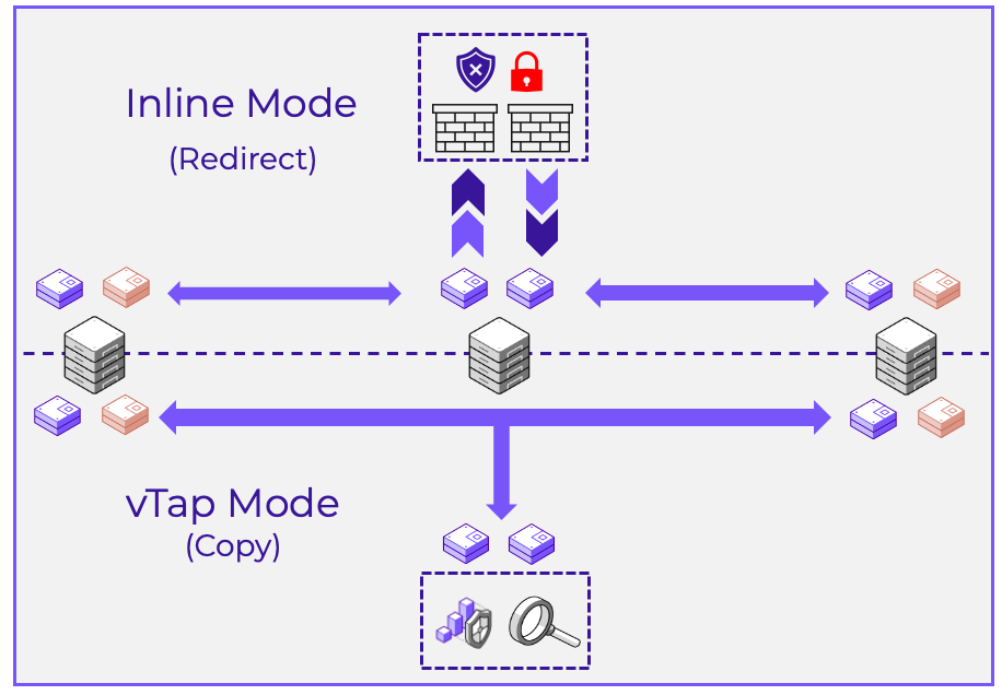
Service Insertion is enabled on a per-rule basis, and is only available for VLAN-scoped Application or Shared Services policies. Service Insertion is currently not available for Global- or VPC-Scoped policies.
Now that you know the various components and how they work individually, let’s explore using them together for scenarios you’re likely to encounter. This section is based on real-world deployments.
The first point to consider is deploying and controlling access to the management and control plane that orchestrates Flow Network Security.
Prism Central and the Network Controller form the management and control plane, respectively, for Flow Network Security. All policy edit operations happen in Prism Central. The Network Controller on the other hand is responsible for pushing the correct policies into the data plane on the AHV hosts.
It is recommended that Prism Central be deployed as a Scale Out cluster to ensure high availability of the management plane and, in the case of the integrated Network Controller, the control plane. Failure of the management plane and control plane does not immediately impact policy enforcement. However, the management and control plane are responsible for installing rules when a VM migrates from host to host as well as updating rules when enforcement criteria (category membership, address/service group modification, etc) change. During a management or control plane failure, these actions will not occur, and security posture will eventually drift from the desired configuration as VMs migrate between hosts while Prism Central while the Network Controller are unavailable.. With a Prism Central Scale Out deployment, the likelihood of such an event is greatly reduced.
Flow Network Security introduces a few additional considerations regarding Prism Central sizing. Refer to the Configuration Maximums page on the Nutanix Support Portal for the latest published configuration maximums.
Security Policies are crucial for the operation of a system, and restricting access to that policy configuration is done using role-based access control. This ensures only authorized users can manage policies.
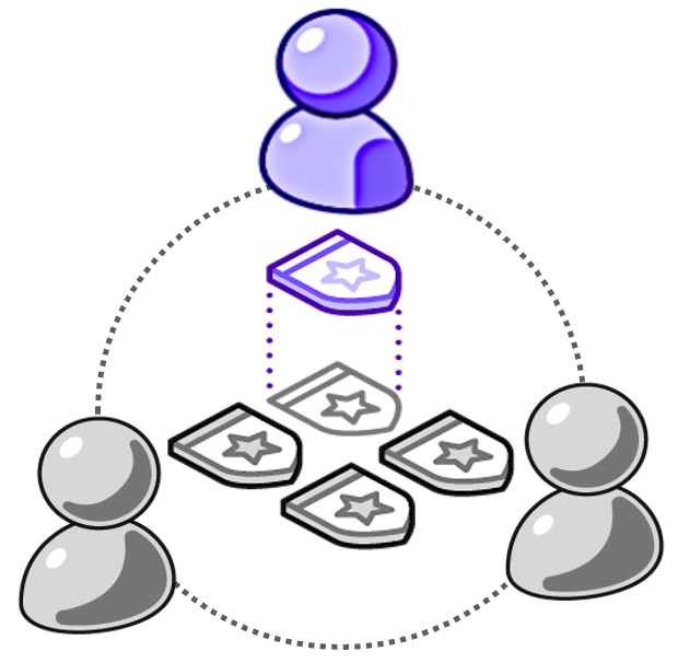
There are three built-in RBAC roles for Flow Network Security, which can be used as-is or cloned to a custom role with modified permissions..
Below are examples for how Flow Network Security can be designed to account for common situations and security requirements.
There are two main policy design methodologies for implementation of microsegmentation. The first is to focus on securing the workloads themselves with ingress policies. The second is to police all unwanted traffic with ingress and egress policies. Both methods are effective in securing virtualized workloads. We will explore both options and how they can be implemented in Flow Network Security, along with the benefits and drawbacks of each.
The Inbound-Focused approach concentrates on securing workloads with ingress policies, while relying on traditional security boundaries, like perimeter firewalls, to prevent unwanted outbound traffic. This is the default approach that Flow Network Security takes in policy creation. Inbound-focused rule-sets rely on perimeter firewalling to define and police north/south traffic, such as Internet-bound traffic.
Consider the following Application Policy for a two-tier application with a web and database component.
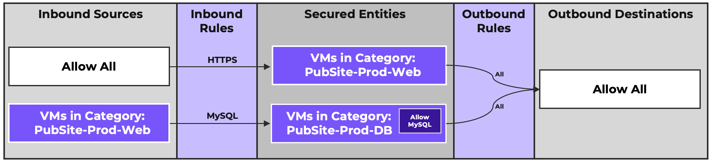
In this policy, we are focused on defining traffic that our application VMs should be permitted to receive. The Web tier is allowed to receive HTTPS traffic from any source, and our Database tier is permitted to receive MySQL traffic from members of the Web Tier. Reminder, according to the App-Centric Policy Model, we also need to consider traffic within a secured entity. Because of this, traffic between database servers is secured via an Intra-Tier rule allowing MySQL traffic.
Meanwhile, all outbound traffic is being allowed, with the assumption that traffic towards external destinations will be secured at an appropriate security boundary like a perimeter firewall. Our workloads themselves remain secure. While we are not restricting the traffic that can be sent by our application (our web servers can, for example, potentially send non-MySQL traffic to our database servers), the ingress policies ensure that any unwanted traffic between Secured Entities is dropped.
The primary benefit to this approach is simplicity and a significantly lower level of effort required to design and implement policies. The primary drawback to this approach is, by allowing all outbound traffic, unwanted traffic to non-VM destinations, such as physical servers and infrastructure, would not be policed unless that traffic were to traverse a traditional firewall. In cases where traditional firewall placement is insufficient or inconvenient, organizations might prefer a more comprehensive approach.
The Defined Outbounds approach requires that all traffic for secured workloads be defined, including application traffic, infrastructure services, and north/south traffic to external destinations. Organizations that desire a “zero-trust” style security posture, especially those with a hybrid cloud or multi-cloud footprint, often prefer this approach.
First, Application-specific Outbound rules must be considered. Consider the same two-tier application as before:
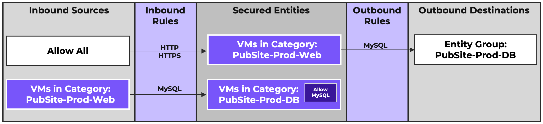
In this case, we need to specifically allow the Web tier to send MySQL traffic to the Database tier. Remember that rules are created solely for, and from the perspective of, the Secured Entity. So, while there is an Inbound rule allowing the Database server to receive MySQL traffic from the Web servers, since the Web servers are themselves Secured Entities, we need to allow them to send the MySQL traffic as well.
Next, infrastructure service traffic (such as DNS, NTP, logging, management, monitoring) and north/south traffic must be accounted for and explicitly allowed this traffic. We could do this within individual application policies, as shown:
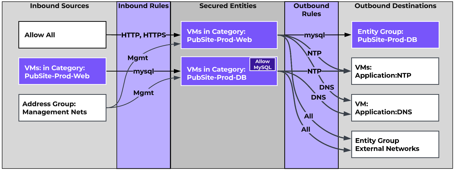
However, this would require that these same services be defined across all application policies. This quickly becomes cumbersome, especially when new services need to be added. A better way is to define policies enabling these rules broadly across the entire environment.
We can build policies that provide access to infrastructure services for our entire infrastructure in a centralized manner. While it is possible to define all of these Infrastructure services and their associated rules in a single application policy, it is recommended that these be split into service-specific Application policies for clarity, as well as to allow service-specific decisions to be made regarding logging, which is on a per-policy basis.
Key Consideration: When defining security policies for infrastructure services, you will often define Secured Entities such as network constructs (VPCs or Subnets) or broad categories that apply to large groups of otherwise unrelated VMs (enforcement state, operating system, environment). You must remember to remove the Intra-Tier rule from these entities, as failure to do so will cause the Intra-Tier rule to override any Inbound or Outbound rules between VMs within the Secured Entity. Keep this in mind when reading through this section and as you build policies in your environment.
A strategy to consider is to define a category that can be applied to all secured VMs, such as Flow:Secured VMs. If there are instances where specific services require more granular definitions, more specific categories can be used. For example, a policy defining management access might allow RDP for Windows servers and SSH for Linux servers. In these cases, more granular categories such as OS:Windows and OS:Linux can be used and combined with the Flow:Secured VMs category by way of an Entity Group.
Consider the following Application Policy examples:
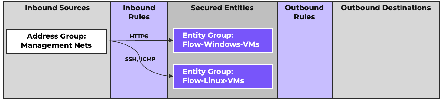
The first policy uses an Address Group defining networks that management traffic might originate from as an Inbound Source, and Entity Groups to define secured Windows and Linux VMs as Secured Entities. We can then define the OS-specific Inbound traffic.
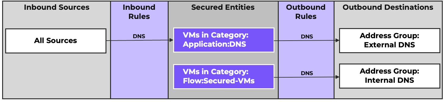
The second policy defines the rules for DNS traffic. DNS servers are allowed to receive DNS traffic from all sources. They are also allowed to send traffic to an address group of defined external DNS servers for forwarding. Our secured VMs are allowed to send DNS traffic to an address group defining internal DNS servers. An address group is used as the destination instead of the Application:DNS category because many organizations have non-VM DNS servers, such as physical domain controllers or a domain controller in a secondary datacenter.
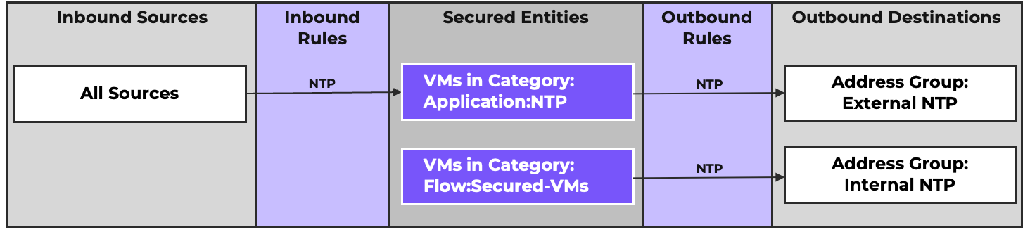
The third policy secures NTP traffic in a similar manner.
Some common infrastructure services are more complex. A primary example is Active Directory. In this case, the definition of an application is left to the discretion of the organization. Two different organizations may have very different thoughts on how to define and organize Directory Services. One organization might build a single policy that defines Domain Controllers, DNS servers, DHCP servers, and certificate servers as Secured Entities, while another might define each of those roles as an Application and choose to split them into distinct policies. The correct approach is the one that makes the most sense to how your organization operates.
When securing Outbound traffic for your VMs & workloads using the comprehensive inbound and outbound approach, all Outbound traffic must be accounted for, including north-south traffic to the Internet or other external destinations.
Allowing Internet Traffic
When creating a security policy, it’s important to remember all of the tools available, and use the right tool for the task at hand. Microsegmentation tools like Flow Network Security are purpose-built for securing internal traffic and east-west traffic, while 3rd party Next-Generation Firewalls deployed at the perimeter excel at securing Internet traffic with advanced threat management capabilities. A common strategy is to configure FNS to allow all Internet-bound traffic, knowing that the perimeter firewall is in place to secure that traffic.
The first step is to clearly define Internet traffic so it can be identified. A reasonable definition would be “any traffic destined for a publicly routable IP address,” and the easiest way to identify this is to first define the IP addresses that are not publicly routable. RFC-6890 defines “Special Purpose IP Addresses”, these addresses are listed below.
0.0.0.0/8
10.0.0.0/8
100.64.0.0/10
127.0.0.0/8
169.254.0.0/16
172.16.0.0/12
192.0.0.0/24
192.0.0.0/29
192.0.2.0/24
192.88.99.0/24
192.168.0.0/16
198.18.0.0/15
198.51.100.0/24
203.0.113.0/24
240.0.0.0/4
255.255.255.255/32
With this information, we can create an address group positively defining the publicly routable ranges. This can be done via 13 IP ranges. We use ranges instead of networks due to efficiency; defining this via CIDR ranges would require 31 networks due to the CIDR boundaries and the rules of subnetting. These ranges are:
1.0.0.0-9.255.255.255
11.0.0.0-100.63.255.255
100.128.0.0-126.255.255.255
128.0.0.0-169.253.255.255
169.255.0.0-172.15.255.255
172.32.0.0-191.255.255.255
192.0.1.0-192.0.1.255
192.0.3.0-192.88.98.255
192.88.100.0-192.167.255.255
192.169.0.0-198.17.255.255
198.20.0.0-198.51.99.255
198.51.101.0-203.0.112.255
203.0.114.0-223.255.255.255
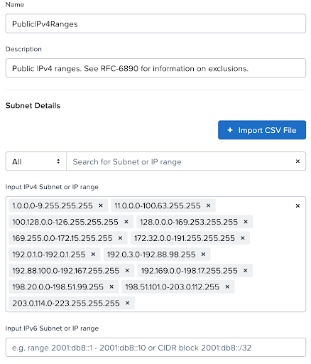
This address group can then be used as an Outbound Destination representing any traffic destined to a public IP.

If your organization owns public IP addresses that are utilized internally, and you wish to exclude these from rules allowing public Internet access, a second address group defining the owned IP ranges can be created. An Entity Group can then be created excluding the owned IP range(s) from the greater PublicSubnets address group.
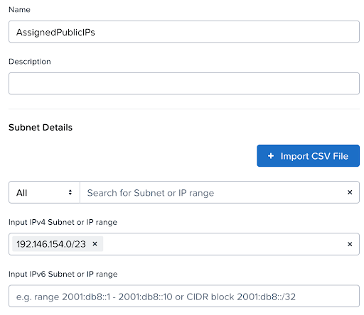
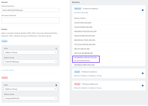

In some cases it may be necessary that all external traffic be allowed, and not just public addresses. For example, if there are IPSEC VPNs terminated on the perimeter firewall, we want to ensure that traffic is allowed to the perimeter where it can be policed and forwarded appropriately. This can also be done with an Entity Group and Exclusions. Define an address group including all internal IP ranges. This address group can then be used as the exclusion criteria for an Entity Group with a base of 0.0.0.0/0. The resulting Entity Group, effectively defining External Networks, can then be used as the destination of a Security Policy as shown:

The examples , so far, have focused on securing VMs by category application. However, this method does leave open the possibility of an uncategorized VM being unsecured. Some organizations may wish for a default policy to be applied automatically to all workloads by default without relying on VM categorization. In Flow Network Security, this can be accomplished by defining a security policy at the network level, using subnets or Flow Virtual Networking VPCs as Secured Entities. When defining a network object, either a a Subnet or a VPC, as a Secured Entity, all VMs (and more specifically, all vNICs) connected to those network objects become part of that Secured Entity.
Consider the following enforced policy:

In this example, the Secured Entity are those Subnets categorized as Flow:Secured-Nets, and by definition, all of the vNICs connected to those Subnets. Note, there are no defined rules. In this example, it is vital that the Flow:Secured-Nets Secured Entity not have an Intra-Tier rule, or else that Intra-Tier rule would override any Inbound or Outbound rules for workloads in those networks.
Per the Application-Centric Policy Model, a Secured Entity with an Enforced policy will only be allowed to send and receive traffic defined via Inbound or Outbound rules. This policy would effectively become a “default deny” for all workloads on those networks that do not otherwise inherit rules from another policy. This is the extreme example of a default deny implementation. Typically, when using network-level entities, they would be used as the Secured Entity in infrastructure service policies that define base level services.
Using the DNS and NTP policy examples previously seen, below is what that would look like. In each example, we have an Inbound rule allowing the service VMs to receive the appropriate service traffic from all sources . The VMs are defined by an Application-keyed category. Outbound rules allow those VMs to reach external resources as needed. Additionally, the subnets categorized as Flow:Secured-Nets are included as a secured entity with an outbound rule allowing them to communicate with internal servers of the respective service. As many environments will have both physical and virtual machines providing these core infrastructure services, an address group is used to allow these outbound rules to include both types of resource. Additionally, we are careful to NOT include an Intra-Tier rule on the Flow:Secured-Nets subnets to ensure we do not override any other inbound or outbound rules for workloads in those subnets.
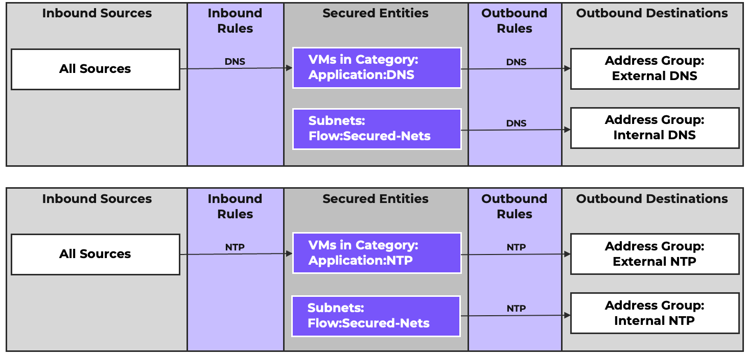
This network-level security is often required by organizations mandating a Zero-Trust security posture, as it ensures that all VMs are secured immediately upon creation.
There is a significant drawback to this approach. Declaring every VM as being within an enforced policy, you can’t use Monitor Mode policies for workloads deployed on these networks, since the enforced policy takes priority. If policy design work is able to be conducted in a separate test/dev environment not subject to these policies, Monitor Mode can be utilized in that environment.
Flow Network Security policies and related objects can be synchronized between Availability Zones to simplify Disaster Recovery. When designing Security Policies for a multi-AZ deployment, it is important to consider whether to use IP-based objects versus Category based. Category-based objects are limited to VMs under the umbrella of the local Prism Central. However, multi-AZ environments often have components that exist in each AZ, whether they are highly-available applications or core infrastructure.
Each Prism Central, or AZ, has its own set of category-to-IP mappings and these mappings are not synced between the AZs. For a policy to work across these AZs we need to expand beyond this single AZ category to IP mapping.
For instance, when running Active Directory in a multi-AZ environment for Disaster Recovery, it is recommended that there be domain controllers deployed in all availability zones to ensure the AD services are available to service machine logon requests as VMs come online during a DR event. Typically, domain controllers must be able to communicate with each other for replication. For this, consider a strictly category-based approach, shown below where the inbounds and outbounds are defined with categories.
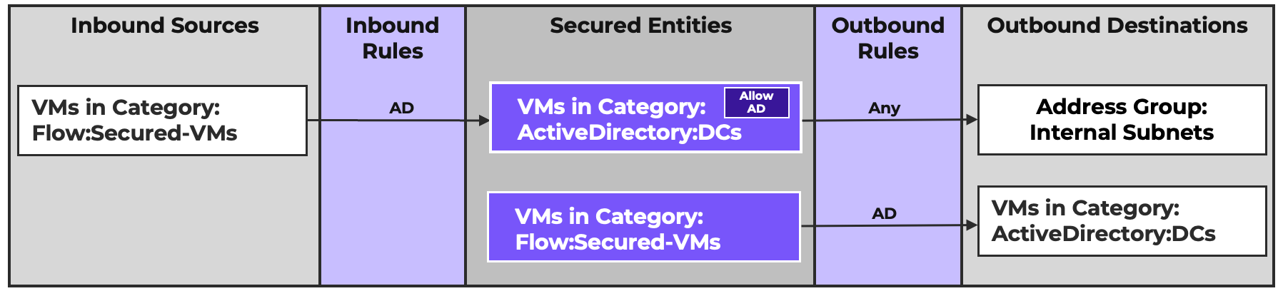
This category-based approach neglects to address instances where AD traffic might need to cross AZ boundaries. An alternative approach using IP-based objects would look like this, where the inbound and outbounds are defined using IP-based address groups:
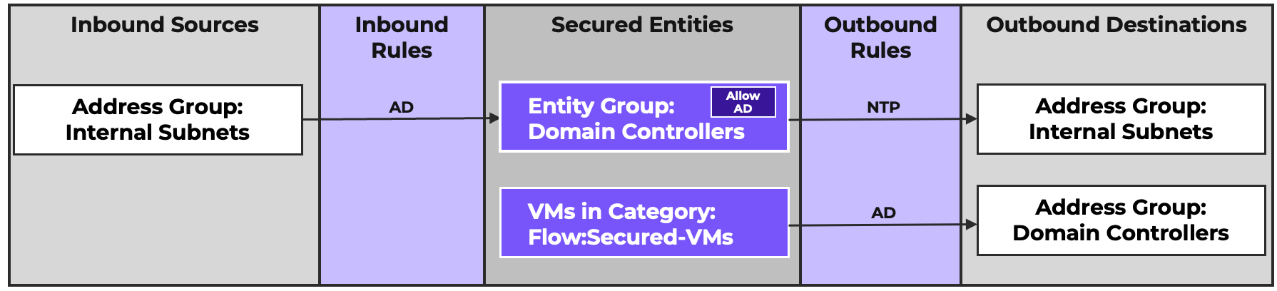
In this case, we also have an Address Group defined that includes all domain controllers across all availability zones. This address group is used to define an Entity Group which acts as a Secured Entity. This Secured Entity will include any VMs with those IP addresses.
Inbound and outbound rules are configured to enable connectivity from resources on internal networks. Finally, the Flow: Secured-VMs category is configured with outbound access to the domain controllers. This policy accomplishes two things. First, it accounts for cross-AZ traffic. Second, it allows the policy and related objects to be synchronized to a second AZ, ensuring that the identical policy is maintained for domain controllers across both AZs. This is a simple example covering a single aspect of Active Directory, but the concept can be similarly applied to any policy that applies to VMs or servers in multiple PC AZs..
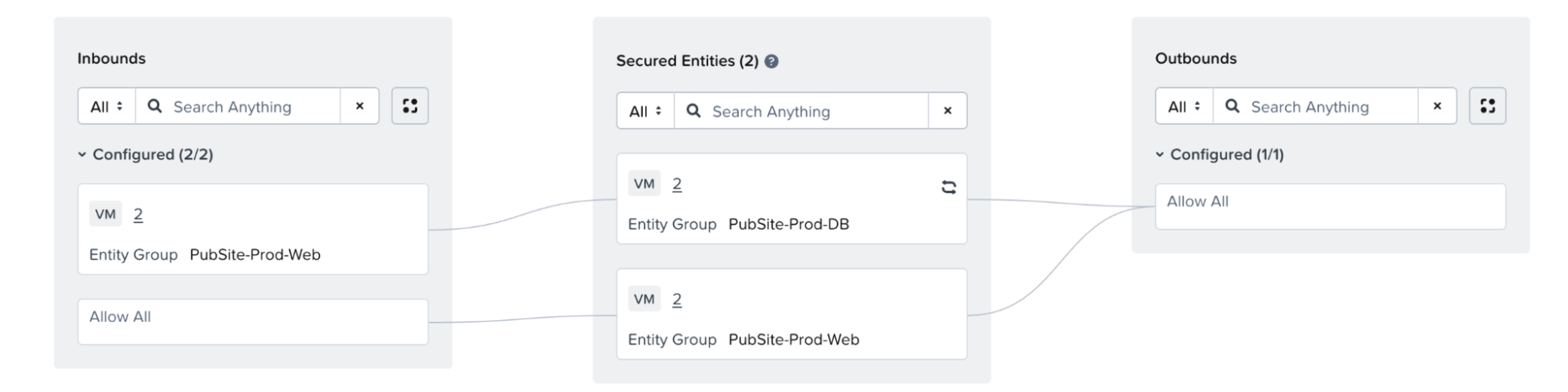
One of the main hurdles to adoption of microsegmentation is lack of documentation on required application traffic flows. Flow Network Security’s Monitor Mode solves this problem by allowing you to observe and visualize your application’s traffic. This traffic data can be used to define the required rules for the application.
The first step of the process is to define the components of your application and appropriately categorize or group the VMs. For example, consider a two-tier application consisting of two web servers and two database servers categorized and grouped accordingly. In this example, the web servers are 100.64.128.10 and 100.64.128.20, and the database servers are 100.64.128.15 and 100.64.128.25. These categories and/or groups become the Secured Entities of the policy. Any known traffic can be added as Inbound and Outbound rules. If there is no known baseline of required traffic, the policy can be left with no rules.
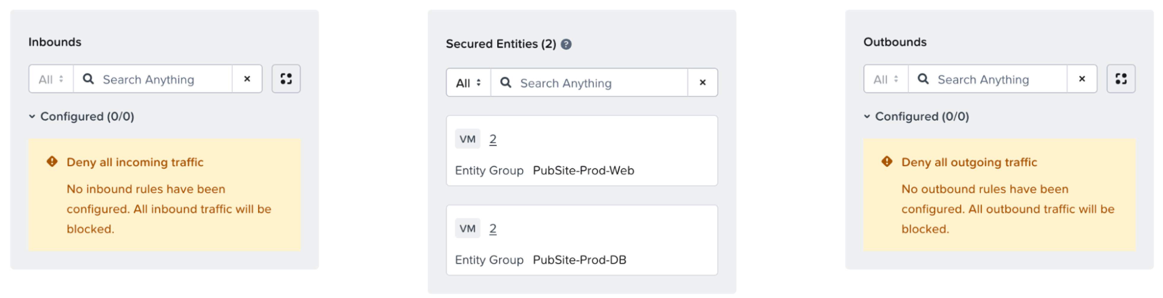
If the policy will eventually be set to Outbound Allow All, leave the Outbound side undefined for now. If an inter-tier flow matches a configured outbound rule, the corresponding inbound traffic will not be visualized. Similarly, if an inter-tier flow matches a configured inbound rule, the corresponding outbound traffic will not be visualized.
In the above example, Web to DB traffic will show up as an outbound flow from the Web tier, and an inbound flow to the DB tier. However, if an Outbound Allow All rule were configured, the corresponding inbound flow will not be visualized, since that traffic would have been allowed. Additionally, Intra-Tier traffic will be visually represented as an outbound flow for that tier. In the above example, DB to DB traffic for database replication will also show up as an Outbound flow. Leaving the Outbound side undefined until all inter-tier and intra-tier traffic is discovered and accounted for will ensure Inter- and Intra-Tier traffic is captured and represented visually.
The Monitoring Mode policy will then observe all new traffic for the Secured Entities, and discovered traffic from the previous 24 hours will be shown in the GUI.
For example, shortly after creating this policy, the following traffic visualization is displayed.
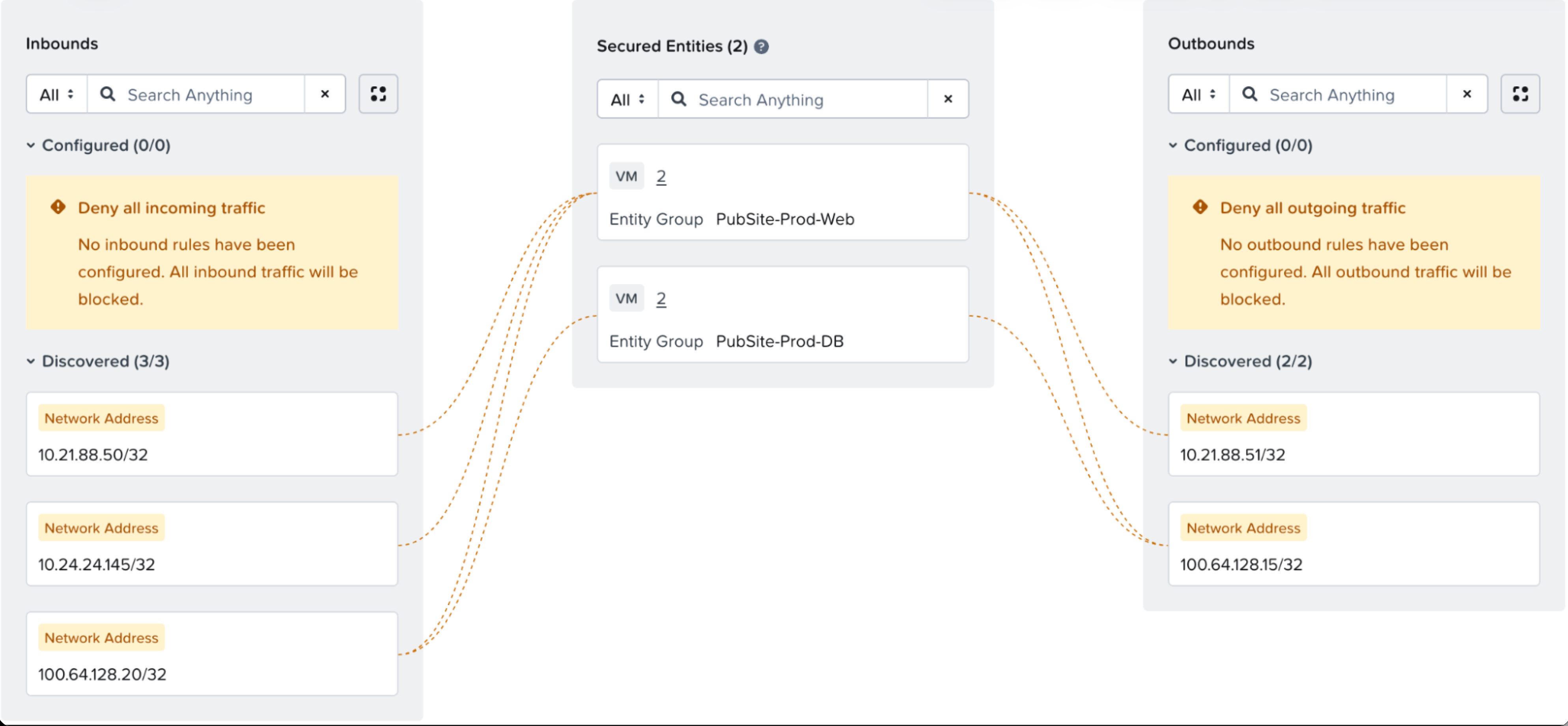
Each yellow line represents an observed traffic flow. By hovering the mouse over the lines, we can see what each flow is. For example, this line shows inbound HTTP traffic received by our web server.:
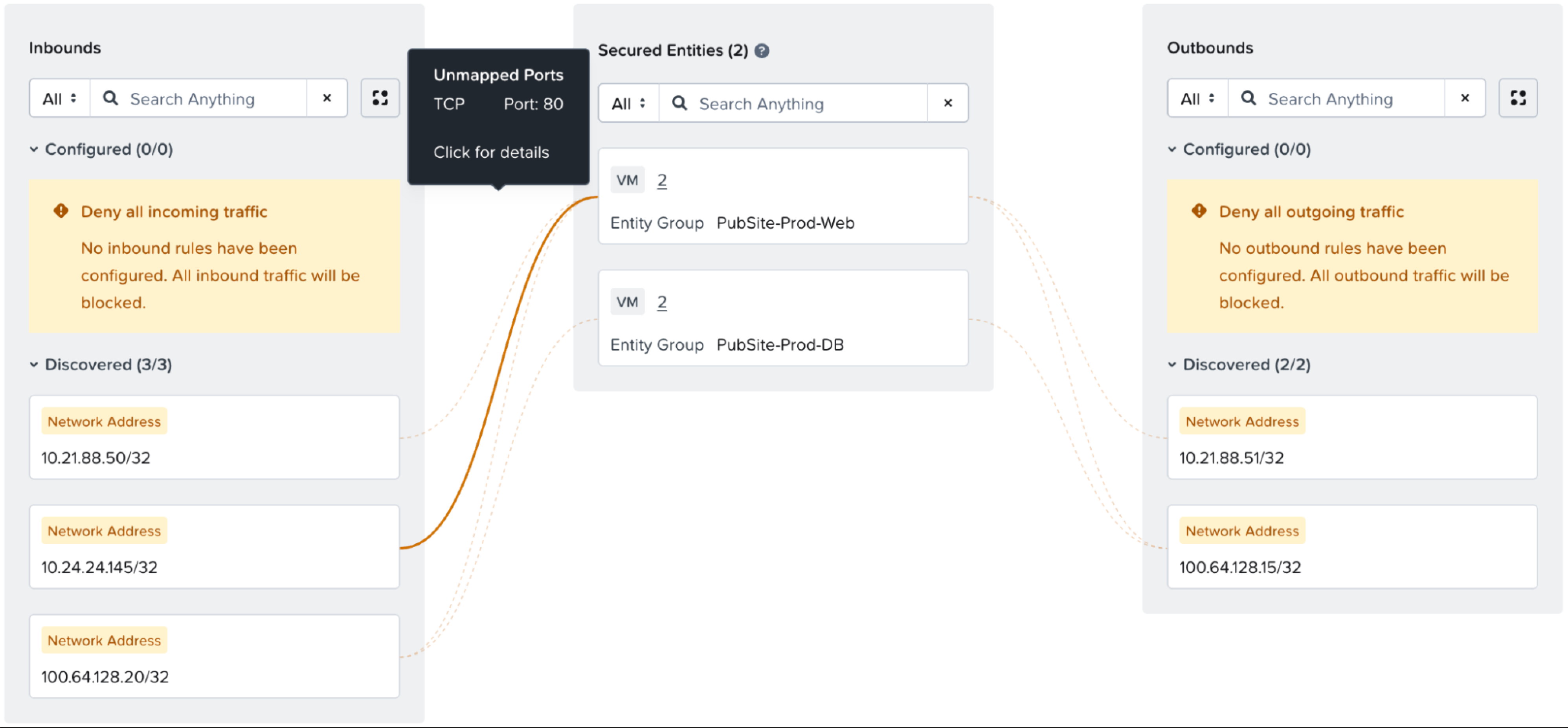
We can look at each line in this way and, if the line reflects traffic that should be allowed, create an appropriate rule. Hovering over each line we see the following:
Now that the Inter- and Intra-tier traffic has been discovered and accounted for in rules, the Outbound Allow All (or specific outbound rules allowing the traffic) can be added.
As visualization traffic shows the past 24 hours, this process should be repeated for a few days, until you are comfortable that all required traffic has been identified and added to the rules. Then your policy is ready for the next step, Enforcement.
In cases of multi-homed VMs, such as load balancers, it is often required that different policies apply to different vNICs. This can be accomplished by way of Entity Groups. Consider a virtual load balancer with a Management vNIC, an outside vNIC and an inside vNIC.
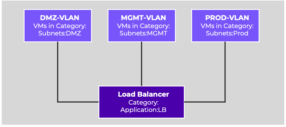
These three vNICs all have different security requirements, and need to be identified individually for use as Secured Entities in policies. By using Entity Groups, we can identify specific vNICs.
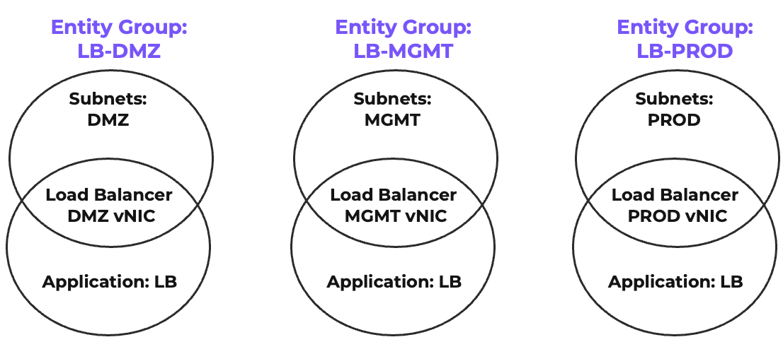
These Entity Groups can then be used to write a security policy ensuring each vNIC can be targeted with appropriate rules.
In summary, this update details how Nutanix Flow Network Security establishes a Zero Trust architecture through agentless, hypervisor-embedded microsegmentation to help neutralize lateral threat movement. This Nutanix Bible section has covered the foundational Application Centric Policy Model core implementation constructs like categories and entity groups, and diverse policy types alongside advanced integrations like the Nutanix Kubernetes Platform and third-party service insertion. Administrators and security architects should use this document as both an architectural blueprint and an operational guide to safely discover, design, and enforce granular security rules, whether utilizing Monitor Mode for traffic visualization or implementing complex, network-level and NIC specific multi-homed VM policies.
As security landscapes and hybrid cloud environments continuously adapt, maintaining an up-to-date defensive posture is critical. Please routinely check this page for updates and be sure to consult the Nutanix Support Portal to review the most recent configuration maximums, deployment guidelines, and software feature enhancements beyond version 7.5. Keeping pace with these ongoing updates ensures your distributed security strategies remain highly performant, resilient during disaster recovery events, and aligned with evolving Nutanix best practices.
©2025 Nutanix, Inc. All rights reserved. Nutanix, the Nutanix logo and all Nutanix product and service names mentioned are registered trademarks or trademarks of Nutanix, Inc. in the United States and other countries. All other brand names mentioned are for identification purposes only and may be the trademarks of their respective holder(s).