» Download this section as PDF (opens in a new tab/window)
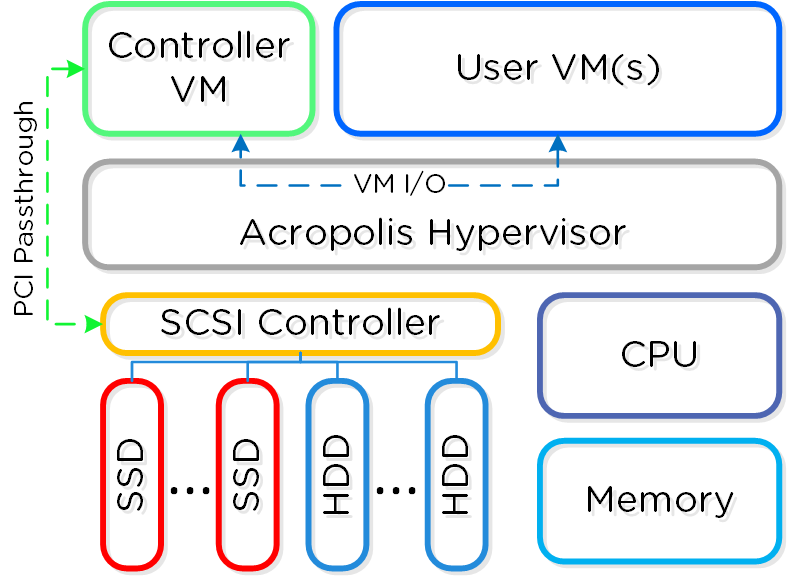
In AHV deployments, the Controller VM (CVM) runs as a VM and disks are presented using PCI passthrough. This allows the full PCI controller (and attached devices) to be passed through directly to the CVM and bypass the hypervisor. AHV is based upon Linux, QEMU, and KVM. Full hardware virtualization is used for guest VMs (HVM).
 AHV Node
Within KVM there are a few main components:
The following figure shows the relationship between the various components:
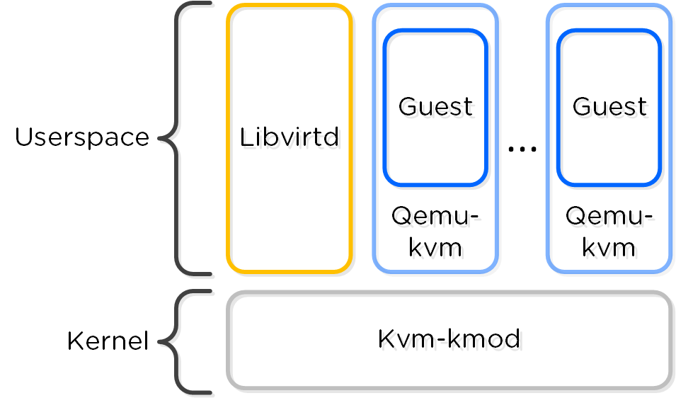 KVM Component Relationship
Communication between AOS and KVM occurs via Libvirt.
Similar to VMware's Enhanced vMotion Capability (EVC) which allows VMs to move between different processor generations; AHV will determine the lowest processor generation in the cluster and constrain all QEMU domains to that level. This allows mixing of processor generations within an AHV cluster and ensures the ability to live migrate between hosts.
The following configuration maximums and scalability limits are applicable:
*The 64TB max vdisk size is the size that has been internally tested by Nutanix Engineering.
The above are true as of AHV 20230302.100173 and AOS 6.8. Refer to Configuration Maximums for other versions.
The following sections outline key capabilities of Nutanix AHV compute for workload management.
AHV has always had the image library which focused on capturing the data within a single vDisk so that it could be easily cloned, but input from the admin was needed to complete the process of declaring the CPU, memory and network details. VM Templates take this concept to the next level of simplicity and provides a familiar construct for admins that have utilized templates on other hypervisors.
AHV VM Templates are created from existing virtual machines, inheriting the attributes of the defining VM such as the CPU, memory, vdisks, and networking details. The template can then be configured to customize the guest OS upon deployment and can optionally provide a Windows license key. Templates allow for multiple versions to be maintained, allowing for easy updates such as operating system and application patches to be applied without the need to create a new template. Admins can choose which version of the template is active, allowing the updates to be staged ahead of time or the ability to switch back to a previous version if needed.
One of the central benefits of virtualization is the ability to overcommit compute resources, making it possible to provision more CPUs to VMs than are physically present on the server host. Most workloads don’t need all of their assigned CPUs 100% of the time, and the hypervisor can dynamically allocate CPU cycles to workloads that need them at each point in time.
Much like CPU or network resources, memory can be overcommitted also. At any given time, the VMs on the host may or may not use all their allocated memory, and the hypervisor can share that unused memory with other workloads. Memory overcommit makes it possible for administrators to provision a greater number of VMs per host, by combining the unused memory and allocating it to VMs that need it.
AOS 6.1 brings memory overcommit to AHV as an option to allow administrators flexibility in environments such as test and development where additional memory and VM density are required. Overcommit is disabled by default and can be defined on a per-VM basis allowing sharing to be done on all or just a subset of the VMs on a cluster.
Different types of applications can have requirements that dictate whether the VMs should run on the same host or a different host. This is typically done for performance or availability benefits. Affinity controls enable you to govern where VMs run. AHV has two types of affinity controls:
TPM technologies are designed to provide enhanced security and privacy in handling encryption operations. The purpose of the TPM is to ensure information storage is better protected from unauthorized access. The primary use case is storing secrets, making it difficult to access them without proper authorization.
The Trusted Computing Group outlines the TPM as a dedicated hardware chip that is soldered onto the motherboard in the computer, which works great in a bare metal deployment. In a virtualized environment using a hypervisor such as AHV or ESXi, the physical TPM chip approach does not scale to support multiple guest OS running on a single hardware configuration due to the following limitations.
To address the scaling issues for a virtualized environment, the hypervisor vendors have implemented a hypervisor-level software called virtual TPM (vTPM), which conforms to the Trusted Computing Group’s TPM specification. vTPM emulates these TPM specifications in the same functional manner as a physical TPM chip creating a private TPM instance per VM guest within the hypervisor. vTPM allows each VM guest to have its own key storage, isolating it from the other guests running on the same physical server. To maintain this isolation, the vTPM does not use the hardware physical TPM chip on the server.
Each hypervisor vendor is responsible for protecting the vTPM instance from outside access. Nutanix AHV, for example, ensures isolation between VMs and encrypts vTPM data using a secure distributed secrets service called Mantle, preventing unauthorized access or tampering.
Live migration allows the system to move VMs from one host to another while the VM is turned on without workload interruption, regardless of whether the administrator or an automatic process initiates the movement. Live migrations occur regularly in the cluster nodes, triggered by maintenance operations, ADS workload balancing, node expansion, or administrator-driven requests.
You can also use live migration to migrate VMs to another physical cluster in the same location or in a different location to rebalance workloads, run maintenance operations, or avoid planned interruptions. For cross-cluster live migrations, we recommend a network with 5ms of latency and support a maximum 40ms latency between clusters.
There are several stages to a VM live migration:
Step 2, the copying of the VM’s memory, can occur over and up to a specific number of iterations (50 at the time of writing). As the VM is still running, AHV will keep track of the VM’s memory which is actively being modified during the copy process in each iteration. Once an iteration is complete, AHV will analyze the amount of memory that has changed and still needs to be copied over to the destination, as well as the achieved rate of memory transfer over the network, to determine if another iteration is required or if the migration can proceed to the next step. The rate at which a VM is modifying memory is more important to a successful migration than the amount of memory in a VM, so AHV will proactively manage the speed of the VM to reduce the amount of memory needing to be sent in the next iteration.
Step 3, pausing of the VM on the source host, will only occur when AHV detects it can transfer the remaining memory in 300ms or less, ensuring that the VM will respond on the destination host after a very short period. This is the maximum stun window. If the remaining memory cannot be transferred within this window after the final iteration, then the migration can abort with a ‘failure to converge’ error. The migration may be automatically re-tried by ADS, host evacuation, or by the administrator manually triggering another migration.
Step 5, updating the network switches, is enacted by sending a RARP broadcast network packet to all devices on the subnet while the VM is being brought up. This ensures that external network switches are aware of where the VM is now running and can route packets appropriately, for example ensuring that TCP connections are not lost during the migration.
There are a range of applications that use the Generation ID to access a virtual machine identifier to validate if the VM was cloned or duplicated for licensing or functionality verification. Starting in AOS release 6.7, AHV creates a Generation ID for each VM that is created, which applications running inside of that VM have access to. Applications can then make decisions on how they want to behave based on whether the correct Generation ID is present. One notable example where this is important is in the case of Windows domain controllers, which can experience problems if accidentally cloned or rolled back without proper safeguards. Generation ID is a mechanism that provides this information to a VM, allowing these restrictions to be tested and enforced by the app.
Advanced Processor Compatibility (APC) streamlines upgrades and helps the transition of clusters to the latest generation CPUs. Clusters are no longer limited by the lowest common denominator CPU. VMs can now accurately identify and utilize the CPU features available to them, improving migrations.
APC offers flexibility in a few different ways. First, clusters can be leveled for consistent CPU presentation to guest VMs, which is the default behavior. Also a baseline CPU model can be set on a per-VM basis for on-demand cross-cluster live migration to different generations of hardware.
Automatic Cluster Selection makes it easy for Nutanix administrators to deliver a cloud-like experience with minimum management overhead. Many organizations have general-purpose environments with multiple clusters managed by a single Prism Central instance, but the utilization of the different clusters previously had to be manually managed by an administrator.
Automatic Cluster Selection intelligently determines the optimal cluster for VM deployment based on resource availability, host affinities, project specifications, and image distribution policies when a VM is created. This capability ensures that resources are automatically balanced across the clusters as new VMs are deployed. Automatic Cluster Selection also saves valuable time helps evenly distribute workloads for maximum performance and utilization across the infrastructure.
ADS, the Acropolis Dynamic Scheduler, is a key component in the AHV stack. ADS is responsible for VM migrations and placements during many operations including resolving host hotspots (hosts with high CPU and storage usage), maintaining High Availability guarantees, optimizing VM placement to free up resources, and enforcing administrator-defined policies. ADS is always running in the background, continuously monitoring and optimizing the infrastructure.
Key features of ADS include:
As ADS focuses on hotspot mitigation and has cost-minimizing remediation plans, this results in fewer VM movements than would be required for an active load-balancing scenario.
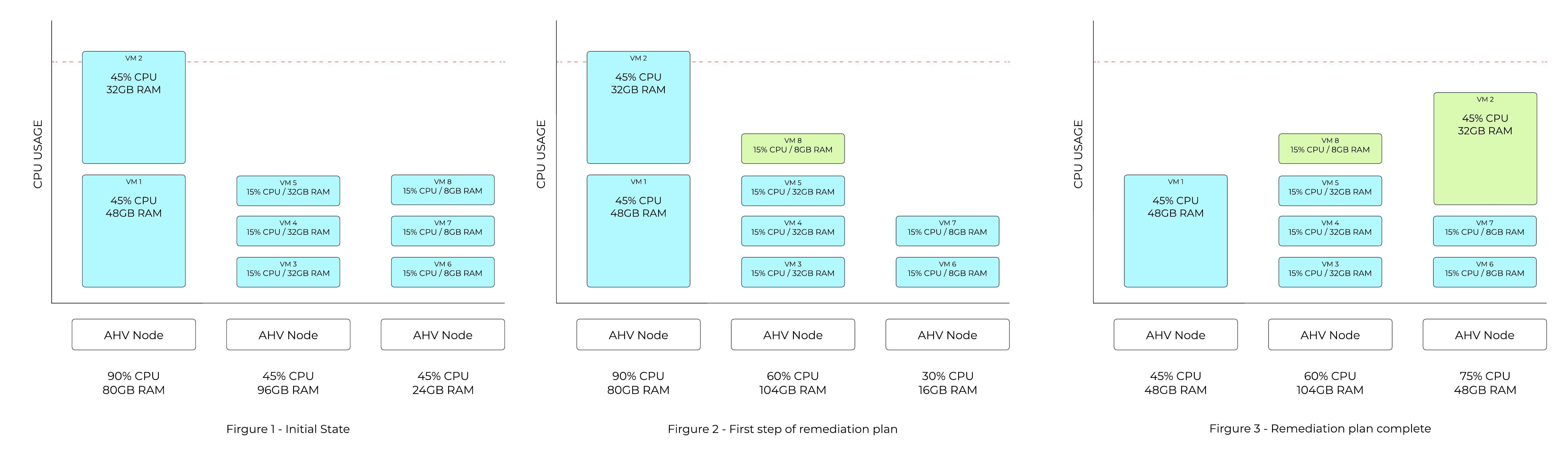
Figure 1 in the following example shows a host utilizing 90% of available CPU capacity. The CPU hotspot threshold is 85%, so ADS identifies that VM movements are required.
In Figure 2, ADS computes a plan that will move one of the 8GB VMs from the third host to the second host, making sufficient space for one of the VMs on the first host to move over.
The amount of memory on each of the VMs on the first host is taken into account when deciding which VM can be moved more easily. The final state in Figure 3 shows the smaller of the two VMs on the first host moving over to the third host as that is the lowest cost move.
 ADS Mitigation Example
ADS plans are usually more complex than this, as multiple dimensions are considered both for hotspot detection and for cost-minimization of the remediation plans.
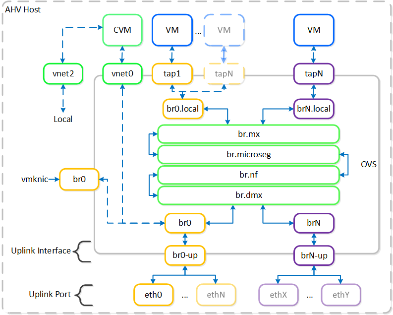
AHV leverages Open vSwitch (OVS) for all VM networking. VM networking is configured through Prism / ACLI and each VM nic is connected into a tap interface.
The following figure shows a conceptual diagram of the OVS architecture:
 Open vSwitch Network Overview
In the prior image you see a few types of components:
OVS is an open source software switch implemented in the Linux kernel and designed to work in a multiserver virtualization environment. By default, OVS behaves like a layer-2 learning switch that maintains a MAC address table. The hypervisor host and VMs connect to virtual ports on the switch.
OVS supports many popular switch features, including VLAN tagging, Link Aggregation Control Protocol (LACP), port mirroring, and quality of service (QoS), to name a few. Each AHV server maintains an OVS instance, and all OVS instances combine to form a single logical switch. Constructs called bridges manage the switch instances residing on the AHV hosts.
Bridges act as virtual switches to manage network traffic between physical and virtual network interfaces. The default AHV configuration includes an OVS bridge called br0 and a native Linux bridge called virbr0. The virbr0 Linux bridge carries management and storage communication between the CVM and AHV host. All other storage, host, and VM network traffic flows through the br0 OVS bridge. The AHV host, VMs, and physical interfaces use “ports” for connectivity to the bridge.
Ports are logical constructs created in a bridge that represent connectivity to the virtual switch. Nutanix uses several port types, including internal, tap, VXLAN, and bond:
Bonded ports aggregate the physical interfaces on the AHV host. By default, a bond named br0-up is created in bridge br0. After the node imaging process, all interfaces are placed within a single bond, which is a requirement for the foundation imaging process. Changes to the default bond, br0-up, often rename this to bond0. Nutanix recommends using the name br0-up to quickly identify the interface as the bridge br0 uplink.
OVS bonds allow for several load-balancing modes, including active-backup, balance-slb and balance-tcp. LACP can also be activated for a bond. The “bond_mode” setting is not specified during installation and therefore defaults to active-backup, which is the recommended configuration.
Briefly mentioned in the prior section, it is possible to balance traffic across bond uplinks.
The following bond modes are available:
You can find additional information on bonds in the AHV networking guide.
AHV supports the following VM network interface types:
By default VM nics will be created as Access interfaces (similar to what you’d see with a VM nic on a port group), however it is possible to expose a trunked interface up to the VM’s OS. Trunked NICs send the primary VLAN untagged, and all additional VLANs as tags to the same vNIC on the VM. This is useful to bring multiple networks to a VM without adding vNICs.
A trunked interface can be added with the following command:
vm.nic_create VM_NAME vlan_mode=kTrunked trunked_networks=ALLOWED_VLANS network=NATIVE_VLAN
Example:
vm.nic_create fooVM vlan_mode=kTrunked trunked_networks=10,20,30 network=vlan.10
AHV Service chaining allows us to intercept all traffic and forward to a packet processor (NFV, appliance, virtual appliance, etc.) functions transparently as part of the network path.
Common uses for service chaining:
Within service chaining there are two types of way:
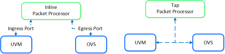 Service chain - Packet Processors
Any service chaining is done after the Flow - Microsegmentation rules are applied and before the packet leaves the local OVS. This occurs in the network function bridge (br.nf):
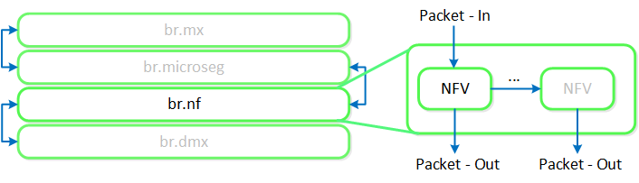 Service Chain - Flow
NOTE: it is possible to string together multiple NFV / packet processors in a single chain. Service chaining is only applicable when Acropolis controls the network stack. Service chaining is not currently supported for network controller-based VLANs or VPCs.
The network controller was released in AOS 6.0 to enable Flow Virtual Networking and VPC overlay subnets. With AOS release 6.7, Nutanix enhanced the network controller, adding support for guest VMs in VLAN-backed subnets. When the network controller is enabled, a new subnet label, VLAN basic is created to describe the existing VLANs managed by the Acropolis leader. Network controller-managed subnets have no label and are simply called VLANs.
Core Use Cases:
Management interfaces(s):
Supported Environment(s):
Prerequisites for network controller-enabled VLANs:
Upgrades:
Deploy Prism Central as extra large for maximum network controller scalability.
The network controller (previously Atlas Network Controller) controls the virtual networking stack used by Flow Virtual Networking VPCs and network controller-enabled VLAN-backed subnets in AHV. The network controller enables configurations at scale and allows for new features such as subnets that exist in multiple Prism Element clusters. This network stack will enable future networking and network security features. With the expanded capabilities, there are a few constructs that are different from what is used in the OVS-based architecture.
The network controller is used to centrally manage and administer VLANs, overlay subnets, IP address pools, and security policies from Prism Central. The network controller runs on Prism Central.
The network controller programs the network control plane and determines how packets are processed. This control plane uses Open Virtual Network (https://www.ovn.org/en/architecture/). A new virtual switch named brAtlas is applied to every AHV host.
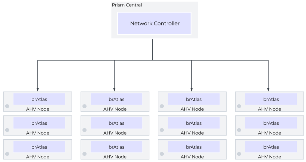 Network Controller Control Plane
There are 2 bridge types used with the network controller, brAtlas and br0.
The bridge brAtlas is a virtual switch that is applied to every AHV host and managed by the network controller. Guest VMs in VPCs and network controller-backed VLANs connect to brAtlas via a tap interface.
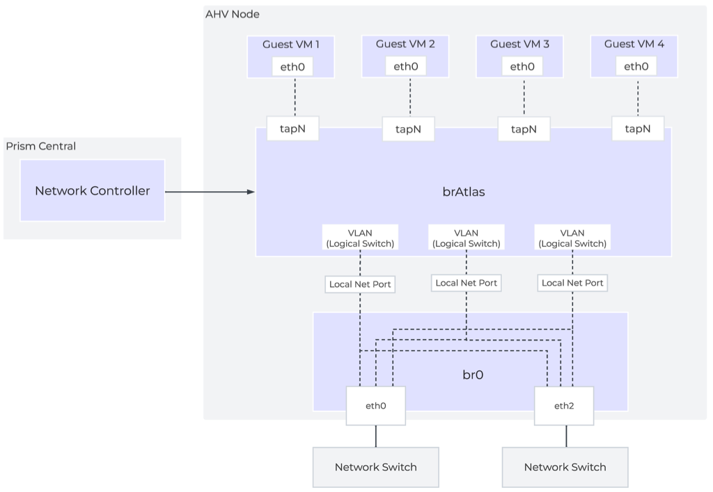 Network Controller Architecture Overview
The bridge br0 is an uplink bridge that functions as a layer 2 switch for brAtlas and connects the physical networks. There can be multiple uplink bridges if required. These additional uplink bridges would follow the same naming construct and be named br0, br1, br2, etc.
For guest VLAN tagging, every VLAN is mapped to a logical switch within brAtlas. Each logical switch will have an associated localnet port connecting to the uplink virtual switch, such as br0. A localnet port is the point of connectivity between logical switches and physical networks.
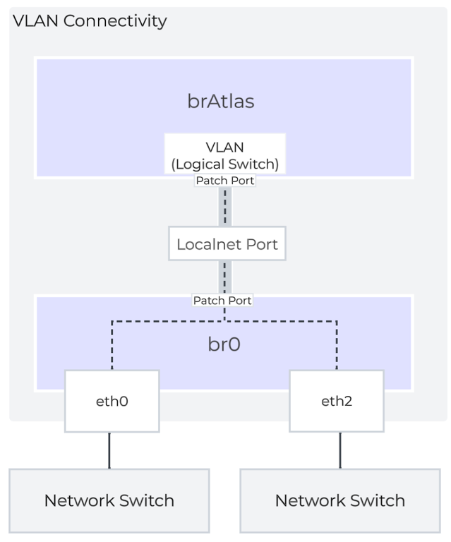
A localnet port is made up of a pair of patch ports between brAtlas and br0. A network controller-enabled VLAN-backed subnet maps to a logical switch in brAtlas.
©2025 Nutanix, Inc. All rights reserved. Nutanix, the Nutanix logo and all Nutanix product and service names mentioned are registered trademarks or trademarks of Nutanix, Inc. in the United States and other countries. All other brand names mentioned are for identification purposes only and may be the trademarks of their respective holder(s).